Composite floor systems and apparatus for supporting a concrete floor

a technology of concrete floor and composite floor, which is applied in the direction of girders, joists, trusses, etc., can solve the problems of increasing the cost of the system, and logistically challenging installation, so as to improve the construction process, reduce the cost, and facilitate the installation

Active Publication Date: 2013-08-27
LIGHTWEIGHT STRUCTURES
View PDF23 Cites 23 Cited by
  • Summary
  • Abstract
  • Description
  • Claims
  • Application Information

AI Technical Summary

Benefits of technology

[0015]A shear connector is secured to the top chord of each joist assembly and extends the entire length thereof. The shear connector extends vertically upwards from the top chord of the joist, having an arcuate end or bend. This bend provides additional surface area to which the concrete layer may bond and can be used to stiffen the shear connector. The shear connector also includes a plurality of openings that also provide additional surface area of contact between the shear connector and the concrete layer, further strengthening the resulting steel-concrete composite flooring system. The shear connector can include attachment portions including downwardly extending tabs for engaging slots provided in the top chord of the joist assembly. By providing a shear connector with attachment tabs and a top chord with corresponding attachment slots, the time it takes to assemble the joist and shear connector members is minimized.
[0017]The composite floor system and methods for supporting a concrete floor eliminate the need for reinforcement provided within the concrete layer, such as rebar, metal mesh or cross braces, thus rendering the system lighter, easier to install and less expensive. In addition, without the necessity to reinforce the concrete, the concrete layer is more suitable for installation of radiant heating systems. Furthermore, construction processes are simplified because cross blocking, special tools and skills required for framing the system during the curing period are not require due to the reduced weight of the system, and the drilling and cutting associated with traditional wood products are all unnecessary. Further, the system provides a composite concrete floor that does not require framing material to be removed, significantly shortening set up and construction time.
[0018]The composite concrete floor support systems disclosed herein have all the advantages of concrete flooring system, such as strength, rigidity, durability, mold resistance and sound attenuation, with the added benefit of utilizing a foam insulation layer to provide a durable and energy-efficient construction. Because of benefits, such as sound attenuation, impact resistance, and high R-value, the foam layer enhances the advantages of the concrete decking to provide a lighter, more durable composite system over traditional composite concrete flooring systems.
[0021]The second embodiment of the composite floor system and methods for supporting a concrete floor eliminates the need for reinforcement provided within the concrete layer, such as rebar, metal mesh or cross braces, thus rendering the system lighter, easier to install and less expensive. In addition, without the necessity to reinforce the concrete, the concrete layer is more suitable for installation of radiant heating systems. Furthermore, construction processes are simplified because cross blocking, special tools and skills required for framing the system during the curing period are not require due to the reduced weight of the system, and the drilling and cutting associated with traditional wood products are all unnecessary. Further, the system provides a composite concrete floor that does not require framing material to be removed, significantly shortening set up and construction time.
[0022]The second embodiment of the composite concrete floor support systems disclosed herein has all the advantages of concrete flooring system, such as strength, rigidity, durability, mold resistance and sound attenuation, with the added benefit of utilizing a foam insulation layer to provide a durable and energy-efficient construction. Because of benefits, such as sound attenuation, impact resistance, and high R-value, the foam layer enhances the advantages of the concrete decking to provide a lighter, more durable composite system over traditional composite concrete flooring systems

Problems solved by technology

The resulting flooring systems are heavy and require significant time to install.
Further, in order to bear the additional weight of the decking and concrete layer during curing, the decking panels must be shored (or braced), adding to the cost of the systems.
In smaller constructions, such as residential applications, these traditional systems were generally too expensive and logistically challenging to install.
Further, in application, conventional concrete flooring systems are subject to significant horizontal and vertical forces, and in particular, horizontal shear occurring along the longitudinal top of primary and secondary joist members.
Indeed, these systems ultimately fail because of loss of interfacial force in the shear span.
However, these studs are welded to the joist after the joist has been connected to the structure during erection, requiring significant labor and time, and they can be hazardous to crew members after installation, but before the concrete has been poured.
Accordingly, this type of composite system, while having increased strength over non-composite systems, can be heavy and expensive due to the added cost of reinforcement material.
However, rebar and other metal reinforcements are subject to corrosion and deterioration of the floor.
Further, in systems where the reinforcement is positioned on top of the top chord or shear connector, these systems are subject to failure due to tearing of the deck near the shear connector.
In addition, many of the prior art systems require removable framing systems to be in place before construction and removed after the concrete has cured, adding to the cost of installation of these types of composite systems.

Method used


Image

  • Composite floor systems and apparatus for supporting a concrete floor
  • Composite floor systems and apparatus for supporting a concrete floor
  • Composite floor systems and apparatus for supporting a concrete floor

Examples


Embodiment Construction

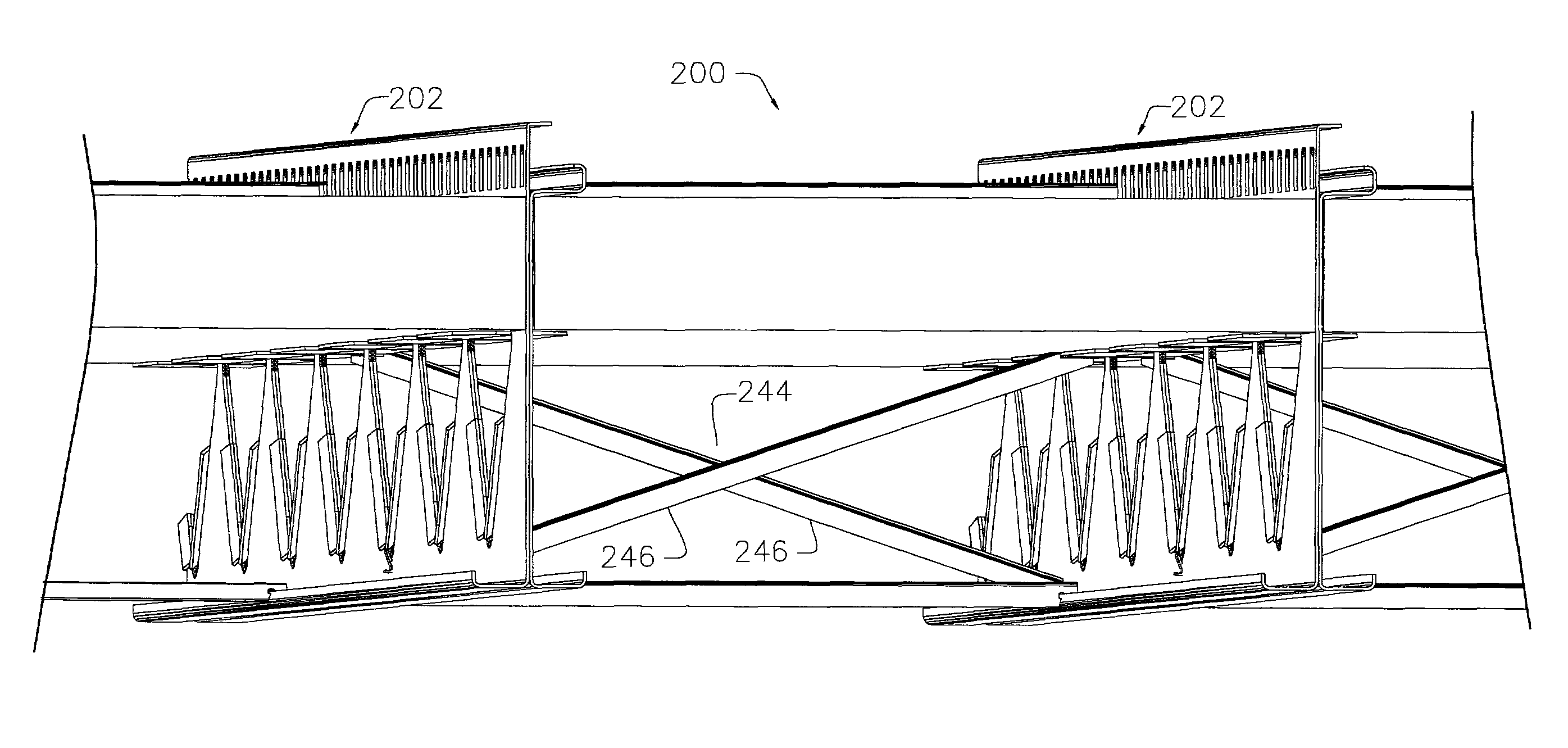
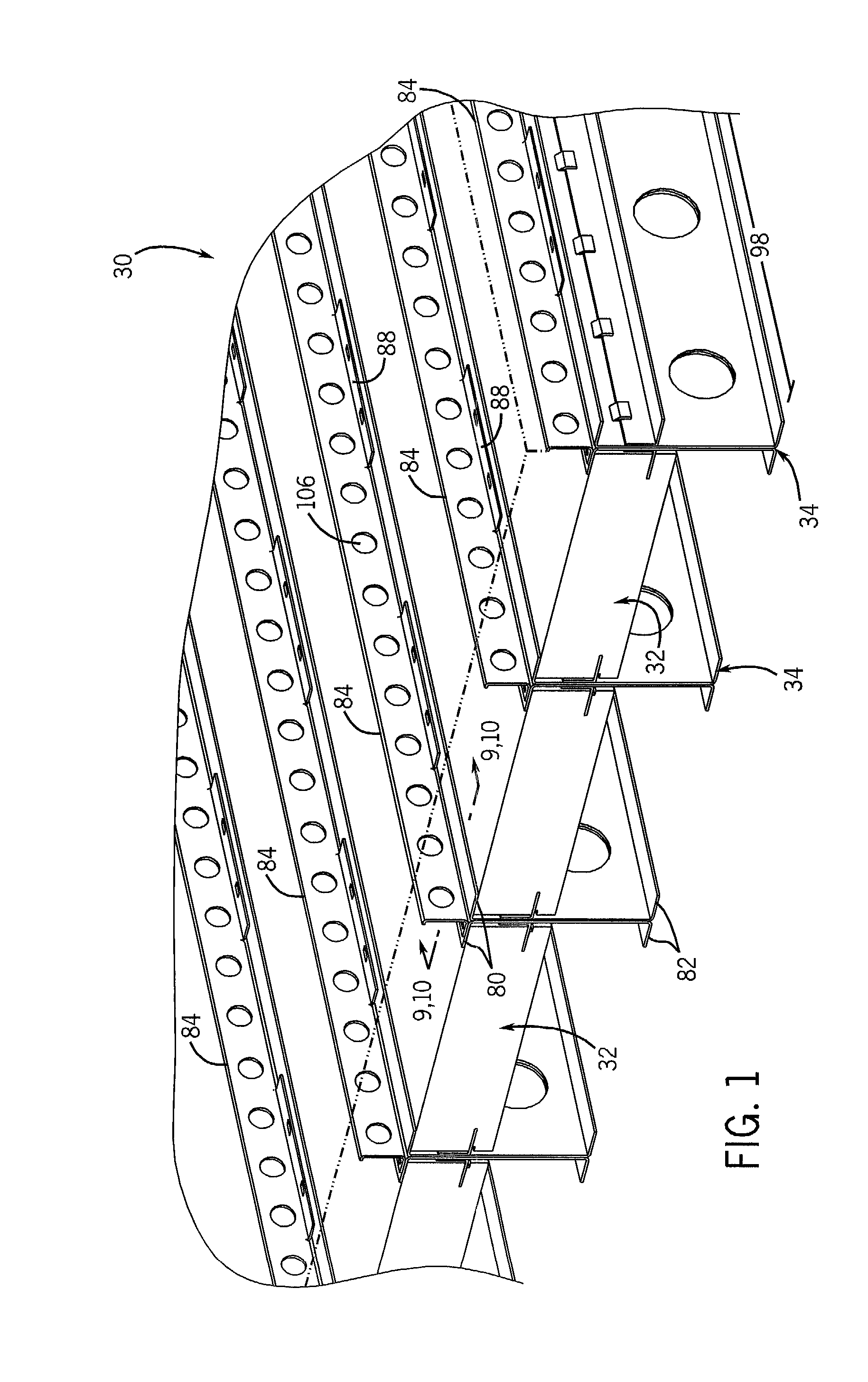
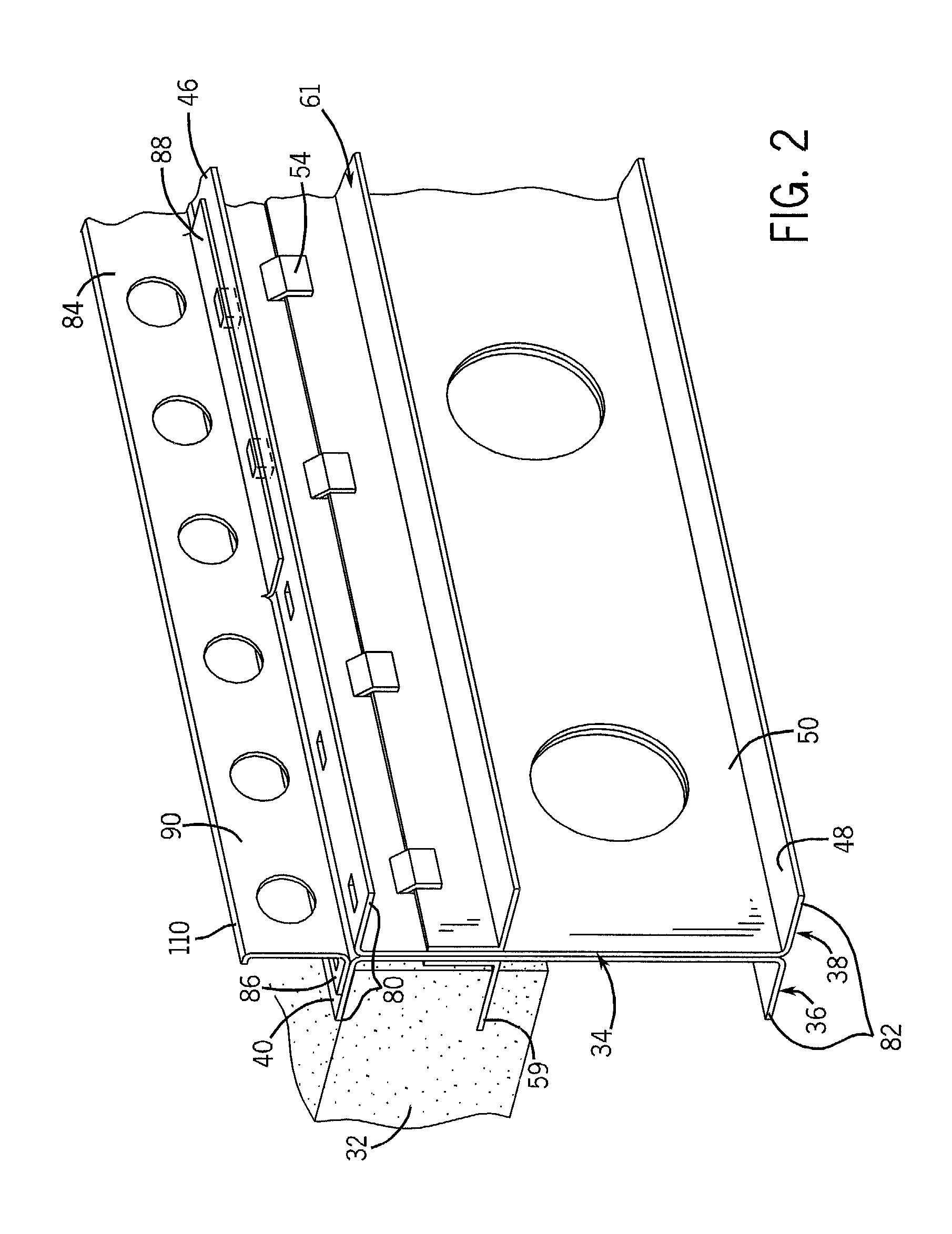
[0060]FIGS. 1 through 10 illustrate one embodiment of a system 30 for supporting a concrete deck or concrete floor in accordance with the present invention. In its simplest form, the floor support system 30 includes at least one panel 32, supported between at least one pair of joist members or assemblies, indicated generally at 34, and a concrete layer 35. As will be readily apparent from the following description, the floor support system is not limited to any particular construction application and can be utilized in grade level or above-grade projects, and in both small and large flooring and / or roofing projects. In addition, the floor support system 30 is compatible with a number of different shoes, hangers and / or connectors, ensuring the system is properly secured to primary structural members such as walls, primary girders, beams, trusses or foundation members, as will be recognized by those skilled in the art.

[0061]Turning first to FIGS. 1-4, each joist assembly 34 comprises ...


PUM


Abstract

An apparatus for supporting a concrete floor includes at least two joist assemblies. Each joist assembly includes a male frame member and a female frame member. A plurality of top joist clips retain a top of the male frame member against the female frame member and a plurality of bottom joist clips retain a bottom of the male frame against the female frame member. A plurality of bottom and top straps are used to retain a distance between two adjacent joist assemblies. A cross brace is used to retain a distance between two adjacent joist assemblies. A deck panel is retained and supported between two adjacent joist assemblies. Concrete is poured over a top of the deck panel to form a composite floor system. An exterior insulating finishing system is attached to the concrete, while it is still wet to form a composite wall system.

Description

CROSS-REFERENCES TO RELATED APPLICATIONS[0001]This is a continuation-in-part application taking priority from Ser. No. 12 / 031,877 filed on Feb. 15, 2008 now abandoned.BACKGROUND OF THE INVENTION[0002]1. Field of the Invention[0003]The present invention relates generally to building components and more particularly to an apparatus for supporting a concrete floor and composite floor systems constructed therewith.[0004]2. Discussion of the Prior Art[0005]Many commercial buildings and some larger, multi-story residential complexes, such as apartment buildings or condominiums, utilize concrete floor decking or concrete floors in their construction. Concrete floor decking has also become increasingly popular in residential and smaller constructions over the last decade. Concrete floor support systems have several advantages over traditional decking materials, such as strength, rigidity, durability, mold resistance, sound attenuation, suitability for in-floor radiant heating and the availa...

Claims


Application Information

Patent Timeline
Patent Type & Authority Patents(United States)
IPC IPC(8): E04B1/18
CPCE04C3/09E04B5/263E04B5/29E04C2003/026E04C2003/0417E04C2003/0452
Inventor JENDUSA, JAMES F.
Owner LIGHTWEIGHT STRUCTURES
Why Eureka
Try Eureka