
Method and an apparatus for installing a communication system using active combiner/splitters

a communication system and combiner technology, applied in the field of wireless communication, can solve the problems of high cost, complex design and installation of such a system, and inability of subscriber stations to operate,

Inactive Publication Date: 2013-08-20
QUALCOMM INC
View PDF61 Cites 19 Cited by
  • Summary
  • Abstract
  • Description
  • Claims
  • Application Information

AI Technical Summary

Benefits of technology

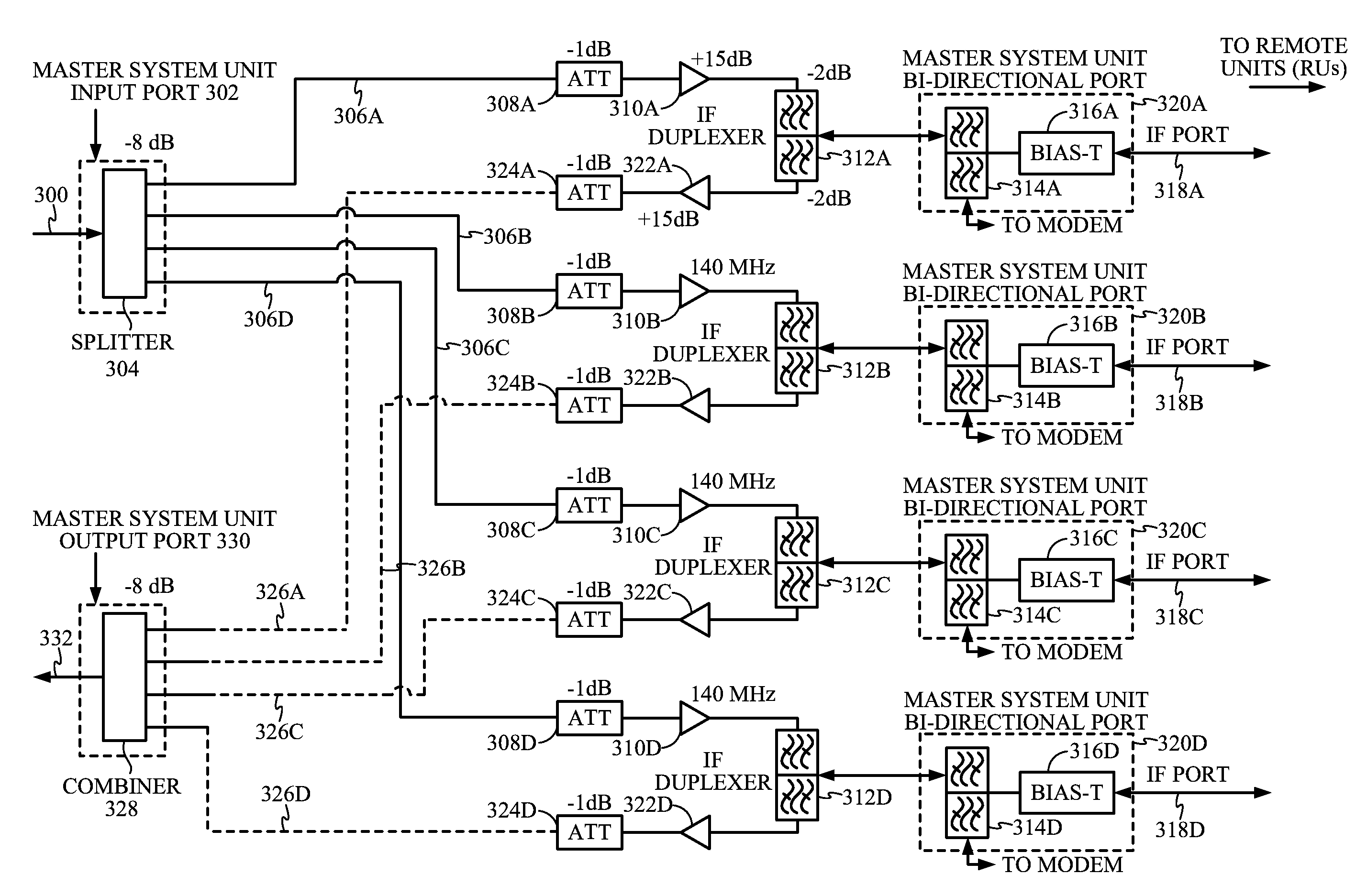
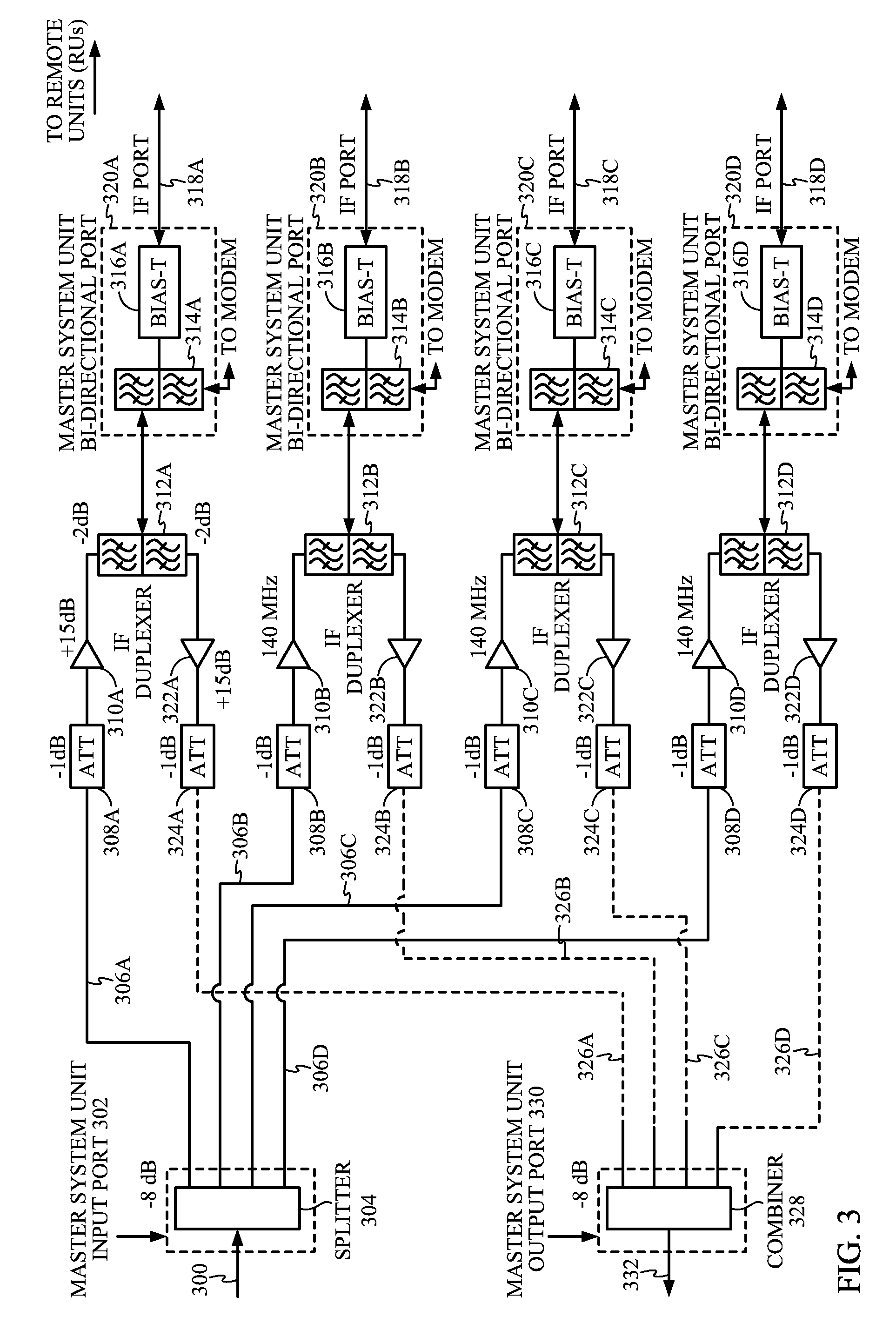
The invention provides a system that allows off-the-shelf equipment to be installed in a wide range of physical sites with varying distances between the main system unit and remote units. The main system unit has an integrated active combiner / splitter that provides bi-directional gain or attenuation in each input / output port to control signal levels. The system also includes a processor that adjusts the gain of each signal based on power levels and the length of the wire line between the main system unit and remote units. The technical effects of the invention include improved signal quality, flexibility in installation, and improved control over signal levels.

Problems solved by technology

When the user does so, the subscriber station may not be able to operate due to the low energy level in the signal that is available to and from the subscriber station.
However, in complex structures, such as buildings having several floors and corridors, a simple relay station is not effective.
One significant problem with such a configuration of the master system unit and remote units is that the design and installation of such a system is expensive and complex.
However, by increasing the gain, signals will over-drive the inputs to closer remote units.
Therefore, it is difficult to provide off-the-shelf integrated equipment that can be used in the wide range of physical sites in which such equipment is required to operate.

Method used


Image

  • Method and an apparatus for installing a communication system using active combiner/splitters
  • Method and an apparatus for installing a communication system using active combiner/splitters
  • Method and an apparatus for installing a communication system using active combiner/splitters

Examples


Embodiment Construction

[0025]FIG. 1 illustrates an in-building communication system 100, which is disclosed in pending patent application entitled “In-building Radio Frequency Coverage,” Ser. No. 09 / 430,616, filed on Oct. 29, 1999. U.S. Pat. No. 6,501,942, which is assigned to the assignee of the present invention and which is incorporated herein by reference in its entirely as if set forth in full herein. The communication system 100 includes a base station 102 that transmits radio-frequency (RF) signals to an antenna 104, which is preferably on top of building 106. Preferably, the RF signal emitted by the base station 102 is a code division multiple access (CDMA) signal.

[0026]A master system unit 108 which is preferably located within the building 106 receives the RF signals transmitted from the base station 102. The base station 102 and the master system unit 108 communicate over the air or via a cable by utilizing a cellular network, digital network, coaxial cable, ethernet cable, or fiber optic lines...


PUM


Abstract

A method and apparatus that allows off-the-shelf equipment to be installed in a wide range of physical sites having a wide range of distances between a master system unit and each of a plurality of remote units. The master system unit has an integrated active combiner / splitter. The active combiner / splitter provides bi-directional gain or attenuation in each of the individual inputs / outputs to allow control of the signal level.

Description

RELATED APPLICATIONS[0001]This application claims priority to U.S. Provisional Application No. 60 / 290,247, filed on May 10, 2001.BACKGROUND OF THE INVENTION[0002]1. Field of the Invention[0003]The present invention relates generally to wireless communications, and more particularly to a method and apparatus for automatically adjusting the amount of gain or loss in a communication system in which signals are relayed between a master system unit and a remote unit in order to compensate for varied environments.[0004]2. Description of the Related Art[0005]Modern communications systems are an important part of our society today. One such communications system is a wireless cellular communication system. In wireless cellular communication systems, communications between users are conducted through one or more base stations. The term forward link is used to refer to communications from a base station to a subscriber station, and the term reverse link is used to refer to communications from...

Claims


Application Information

Patent Timeline
IPC IPC(8): H04B3/36H04B7/14H04W88/08
CPCH04W88/085
Inventor YONA, ELIWEISSMAN, HAIM
Owner QUALCOMM INC
Learn More