
Driver risk assessment system and method having calibrating automatic event scoring

a risk assessment system and automatic event scoring technology, applied in the direction of vehicle position/course/altitude control, process and machine control, instruments, etc., can solve the problems of a system that employs an operational architecture that provides customer users a variety of reporting and review options, and achieves robust and reliable event scoring and reporting, improve reliability, and optimize data transmission bandwidth

Active Publication Date: 2013-08-13
DRIVECAM
View PDF62 Cites 157 Cited by
  • Summary
  • Abstract
  • Description
  • Claims
  • Application Information

AI Technical Summary

Benefits of technology

The present invention relates to a driver risk assessment system and method with calibrating automatic event scoring. The system should provide reliable and accurate event scoring and reporting while optimizing data transmission bandwidth. It should also include onboard event detectors that record data related to detected driving events and selectively store or transfer the data. The system should continue to improve its reliability through regular calibration with human review of automated predictive event reports. The system should also respond to user requests by transferring select data to the user at a variety of locations and formats.

Problems solved by technology

A detailed review of each of these prior systems has been conducted, and while each and every one of them discloses what is purported to be a novel system for vehicle risk monitoring, reporting and / or analysis, none of these prior systems suggests a system that employs an operational architecture that provides customer users a variety of reporting and review options, including automated event scoring, manual event scoring and even no event scoring (i.e., predictive event scoring only).

Method used


Image

  • Driver risk assessment system and method having calibrating automatic event scoring
  • Driver risk assessment system and method having calibrating automatic event scoring
  • Driver risk assessment system and method having calibrating automatic event scoring

Examples


Embodiment Construction

[0022]The following description is provided to enable any person skilled in the art to make and use the invention and sets forth the best modes contemplated by the inventor of carrying out his invention. Various modifications, however, will remain readily apparent to those skilled in the art, since the generic principles of the present invention have been defined herein specifically to provide a Driver Risk Assessment System and Method Having Calibrating Automatic Event Scoring.

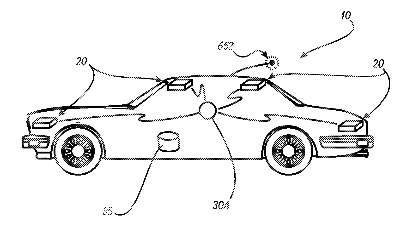
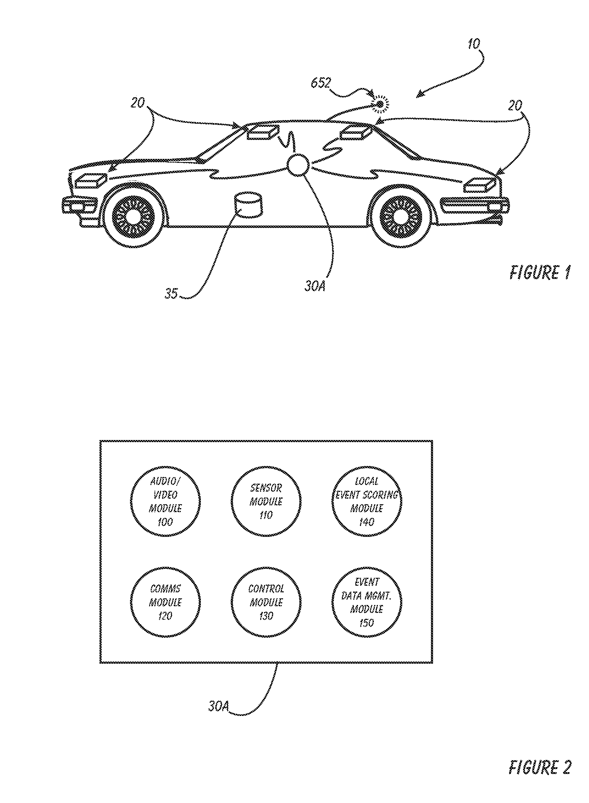
[0023]The present invention can best be understood by initial consideration of FIG. 1. FIG. 1 is a block diagram of a conventional vehicle 10 having a preferred embodiment of the system of the present invention installed therein. The event detector 30A is in control of one or more event capture devices 20 that are attached to the vehicle 10. The event detector 30A communicates with the capture devices 20 via a wired or wireless interface. There is a data storage area 35 also associated with the event detector...


PUM


Abstract

A Driver Risk Assessment System and Method Having Calibrating Automatic Event Scoring is disclosed. The system and method provide robust and reliable event scoring and reporting, while also optimizing data transmission bandwidth. The system includes onboard vehicular driving event detectors that record data related to detected driving events and selectively store or transfer data related to said detected driving events. If elected, the onboard vehicular system will score a detected driving event, compare the local score to historical values previously stored within the onboard system, and upload selective data or data types to a remote server or user if the system concludes that a serious driving event has occurred. Importantly, the onboard event scoring system, if enabled, will continuously evolve and improve in its reliability by being periodically re-calibrated with the ongoing reliability results of manual human review of automated predictive event reports. The system may further respond to independent user requests by transferring select data to said user at a variety of locations and formats.

Description

[0001]This application is a continuation of co-pending U.S. patent application Ser. No. 12 / 814,117, entitled DRIVER RISK ASSESSMENT SYSTEM AND METHOD HAVING CALIBRATING AUTOMATIC EVENT SCORING filed Jun. 11, 2010 which is incorporated herein by reference for all purposes, a continuation in part of U.S. patent application Ser. No. 12 / 359,787, now U.S. Pat. No. 8,269,617 entitled METHOD AND SYSTEM FOR TUNING THE EFFECT OF VEHICLE CHARACTERISTICS ON RISK PREDICTION filed Jan. 26, 2009, which is incorporated herein by reference for all purposes.[0002]This application is an improvement upon the systems, methods and devices previously disclosed in application Ser. No. 11 / 382,222, now U.S. Pat. No. 7,659,827, filed May 8, 2006, 11 / 382,239, now U.S. Pat. No. 8,314,708, filed May 8, 2006, 11 / 566,539 filed Dec. 4, 2006, Ser. No. 11 / 467,694, now U.S. Pat. No. 8,373,567, filed Aug. 28, 2006, Ser. No. 11 / 382,328 filed May 9, 2006, Ser. No. 11 / 382,325 filed May 9, 2006, Ser. No. 11 / 465,765 filed ...

Claims


Application Information

Patent Timeline
Patent Type & Authority Patents(United States)
IPC IPC(8): B60Q1/00
CPCG07C5/085G07C5/008G07C5/0808
Inventor COOK, BRYONGILLES, LOUIS
Owner DRIVECAM
Learn More