
Secondary battery and fabrication method thereof

a technology of secondary batteries and fabrication methods, which is applied in the direction of sustainable manufacturing/processing, cell components, wound/folded electrode electrodes, etc., can solve the problems of cracking, wet spread of the outer circumferential edge of the swaged portion over the surface of the outer terminal,

Inactive Publication Date: 2013-08-13
HITACHI AUTOMOTIVE SYST LTD
View PDF23 Cites 2 Cited by
  • Summary
  • Abstract
  • Description
  • Claims
  • Application Information

AI Technical Summary

Benefits of technology

[0013]According to the 2nd aspect of the present invention, the oxide layer of a secondary battery according to the 1st aspect may assume a film thickness required to minimize wettability of a molten metal at the swage-fused area.
[0025]According to the present invention, an occurrence of defective welding attributable to wet spreading of molten metal, manifesting specifically in a staged portion, can be prevented.

Problems solved by technology

There is an issue yet to be optimally addressed with regard to the battery disclosed in Japanese Laid Open Patent Publication No. 2009-259524 in that when the outer circumferential edge of the swaged portion is welded, the melted outer circumferential edge of the swaged portion may wet spread over the surface of the outer terminal and cracking may occur due to the tensile residual stress manifesting as the melted material solidifies.

Method used


Image

  • Secondary battery and fabrication method thereof
  • Secondary battery and fabrication method thereof
  • Secondary battery and fabrication method thereof

Examples


Embodiment Construction

[0045]An embodiment of the secondary battery according to the present invention is described in reference to drawings.

[0046](Overall Structure)

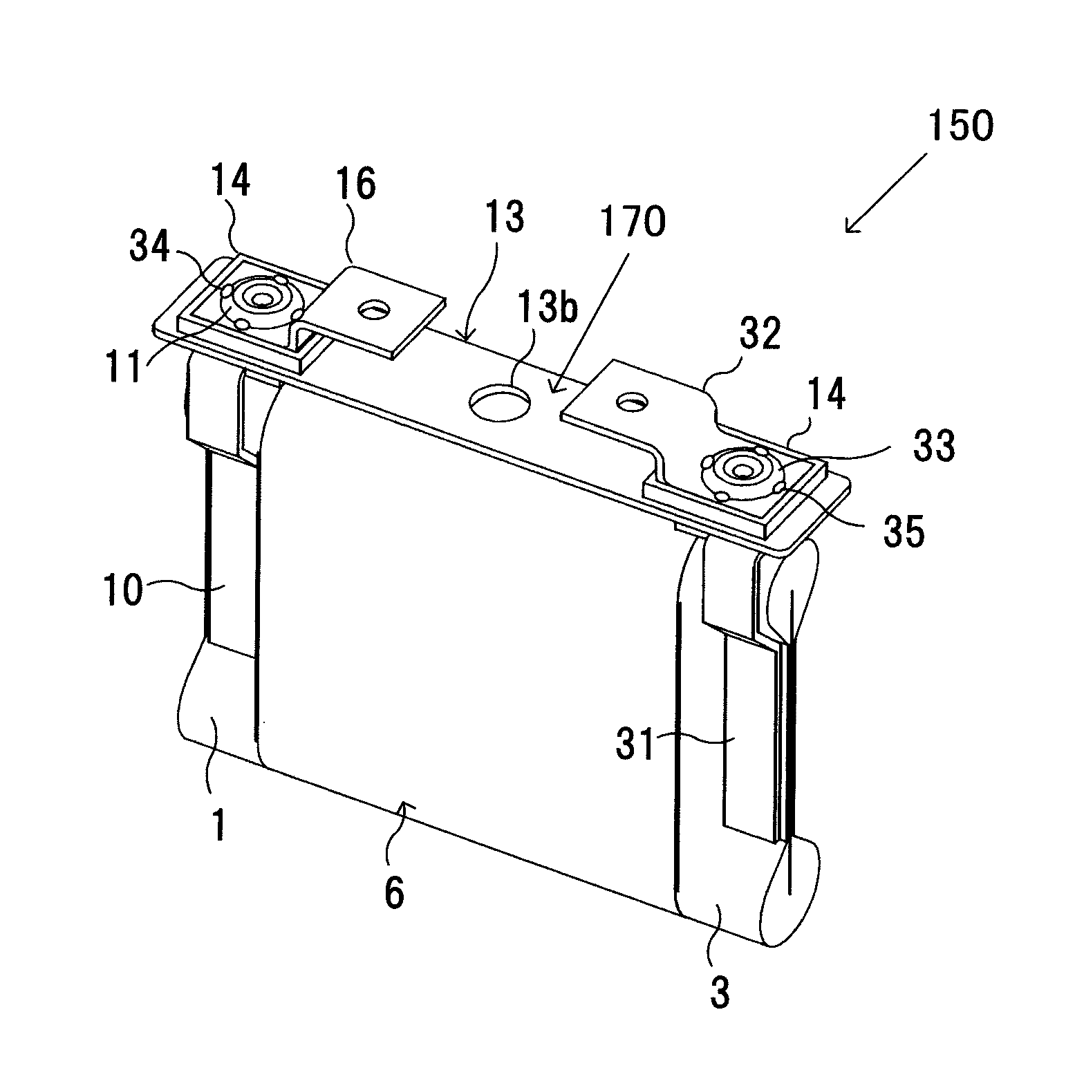
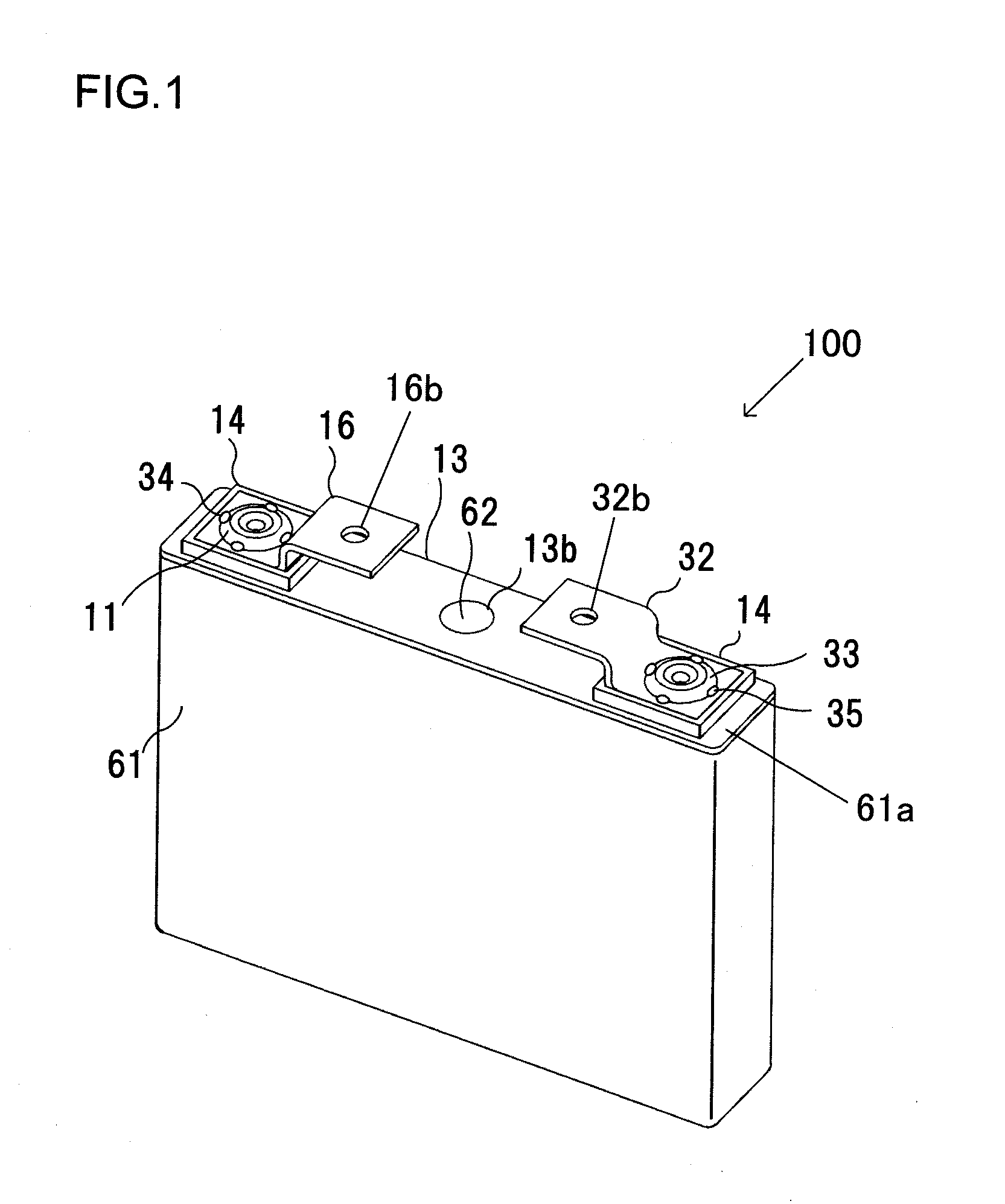
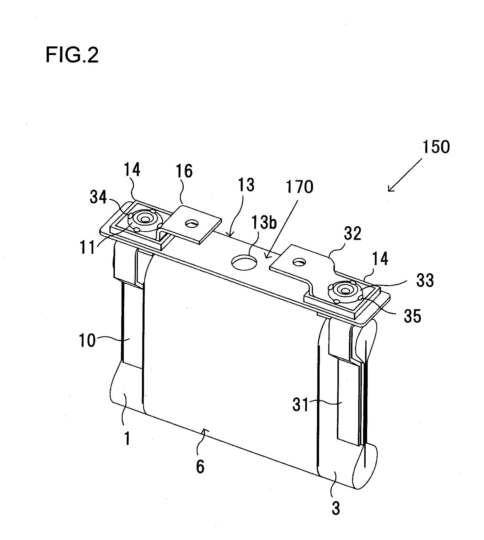
[0047]As shown in FIG. 1, a secondary battery 100 is manufactured by first inserting a lid assembly 150 shown in FIG. 2 into a case 61 and then sealing the case 61. FIG. 2 shows the lid assembly 150 assembled by mounting a jelly roll (winding pack) 6 shown in FIG. 4 at a lid-terminal assembly 170 shown in FIG. 3.

[0048]As shown in FIG. 3, the lid-terminal assembly 170 includes a lid 13 with positive and negative electrode external terminals 16 and 32 and positive and negative electrode current collector plates 10 and 31 mounted thereat. As the lid 13 is welded to the case 61 along the peripheral edges thereof, the case 61 becomes sealed. An electrolyte injection opening 13b is formed at the lid 13 and after the case 61 is sealed, an electrolyte (not shown) is poured into the case 61 through the electrolyte injection opening 13b. Once the case ...


PUM

PropertyMeasurementUnit
thicknessaaaaaaaaaa
thicknessaaaaaaaaaa
pulse energyaaaaaaaaaa

Abstract

A secondary battery includes: a jelly roll that includes a positive and a negative electrode wound via a separator; a case; a lid; and electrically conductive input / output members, wherein: the electrically conductive input / output members include, at least; a positive and a negative electrode current collector plate with one end thereof connected to the positive and the negative electrode respectively; a positive and a negative electrode external conductive member with one end thereof connected to another end of the positive and the negative electrode current collector plate respectively and another end thereof extending to an outer side of the lid; the one end of the positive and the negative electrode external conductive member are respectively swage-fused to the other end of the positive and the negative electrode current collector plate; and an oxide layer is formed at a surface of each swage-fused area.

Description

INCORPORATION BY REFERENCE[0001]The disclosure of the following priority application is herein Incorporated by reference:[0002]Japanese Patent Application No. 2010-197854 filed Sep. 3, 2010BACKGROUND OF THE INVENTION[0003]1. Field of the Invention[0004]The present invention relates to a secondary battery such as a lithium secondary battery and a fabrication method through which the secondary battery is manufactured.[0005]2. Description of Related Art[0006]Among lithium secondary batteries with large capacities (Wh) developed in recent years as motive power sources in hybrid vehicles, electric vehicles and the like, particularly intense interest is focused on prismatic lithium secondary batteries assuring high energy density (Wh / kg).[0007]A prismatic lithium secondary battery includes a flat jelly roll constituted with a winding assembly of a positive electrode formed by coating a positive foil with a positive active material, a negative electrode formed by coating a negative foil wi...

Claims


Application Information

Patent Timeline
Patent Type & Authority Patents(United States)
IPC IPC(8): H01M4/00H01M6/00H01M50/176H01M50/536H01M50/538H01M50/55H01M50/566H01M50/645
CPCB23K35/365H01M2/0217H01M2/0426H01M2/0473H01M2/06H01M2/26H01M2/30H01M10/0431H01M10/0587Y10T29/4911H01M2/365H01M4/667H01M2/263Y02E60/10H01M50/103H01M50/169H01M50/15H01M50/538Y02P70/50H01M50/55H01M50/536H01M50/176H01M50/645H01M50/566
Inventor AOTA, KINYAFUJITA, TOSHIRO
Owner HITACHI AUTOMOTIVE SYST LTD
Learn More