Amplifier using fast discharging reference

a reference and amplifier technology, applied in the direction of pulse generator, pulse technique, electronic switching, etc., to achieve the effect of reducing total harmonic distortion plus noise in the amplifier

Active Publication Date: 2013-07-23
SILICON LAB INC
View PDF9 Cites 1 Cited by
  • Summary
  • Abstract
  • Description
  • Claims
  • Application Information

AI Technical Summary

Benefits of technology

[0011]The present disclosure describes various embodiments of structures and methods, which may, in some embodiments, reduce total harmonic distortion plus noise in an amplifier.

Problems solved by technology

A problem with some of these design objectives is that they can be contradictory.

Method used


Image

  • Amplifier using fast discharging reference
  • Amplifier using fast discharging reference
  • Amplifier using fast discharging reference

Examples


Embodiment Construction

[0011]The present disclosure describes various embodiments of structures and methods, which may, in some embodiments, reduce total harmonic distortion plus noise in an amplifier.

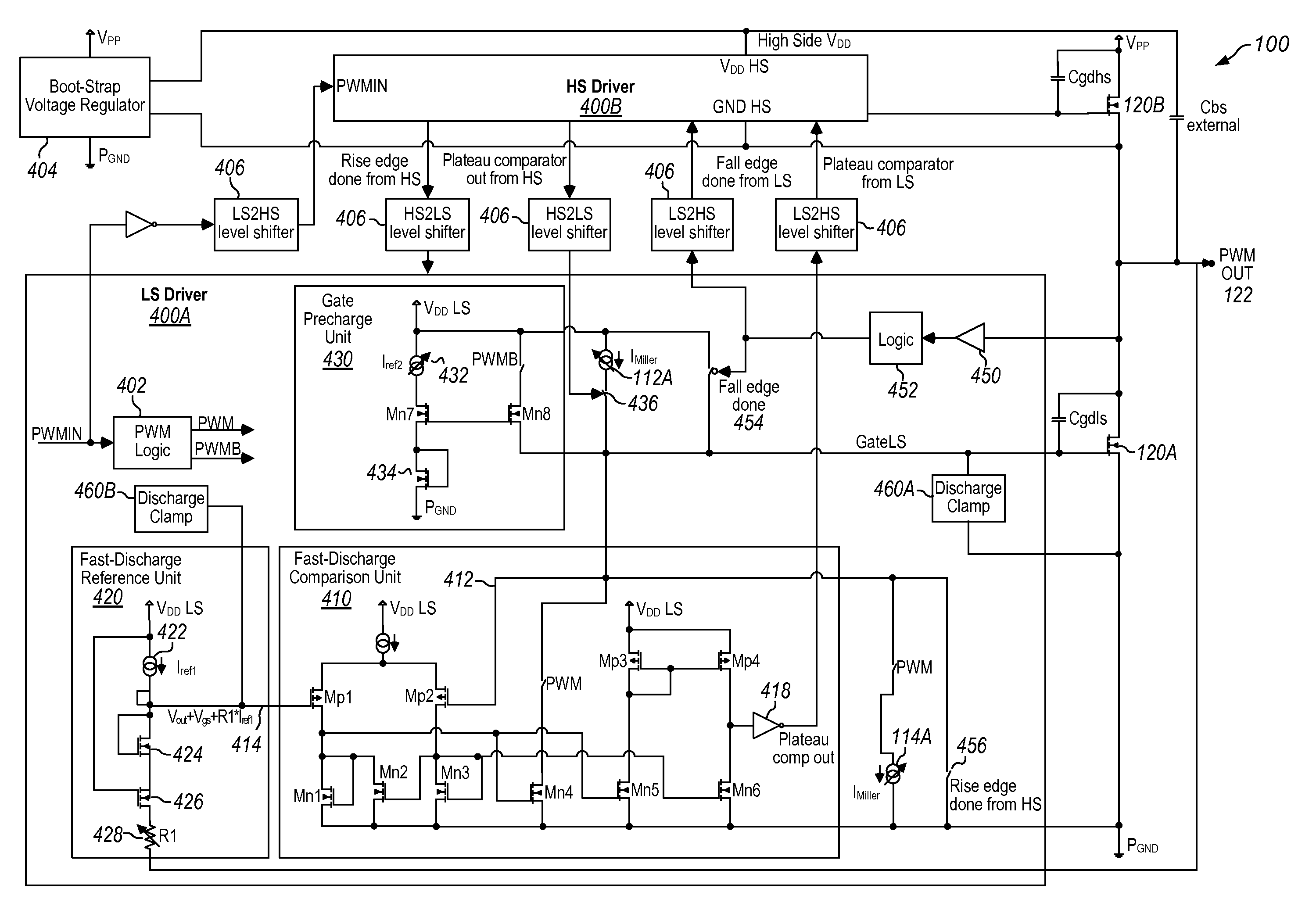
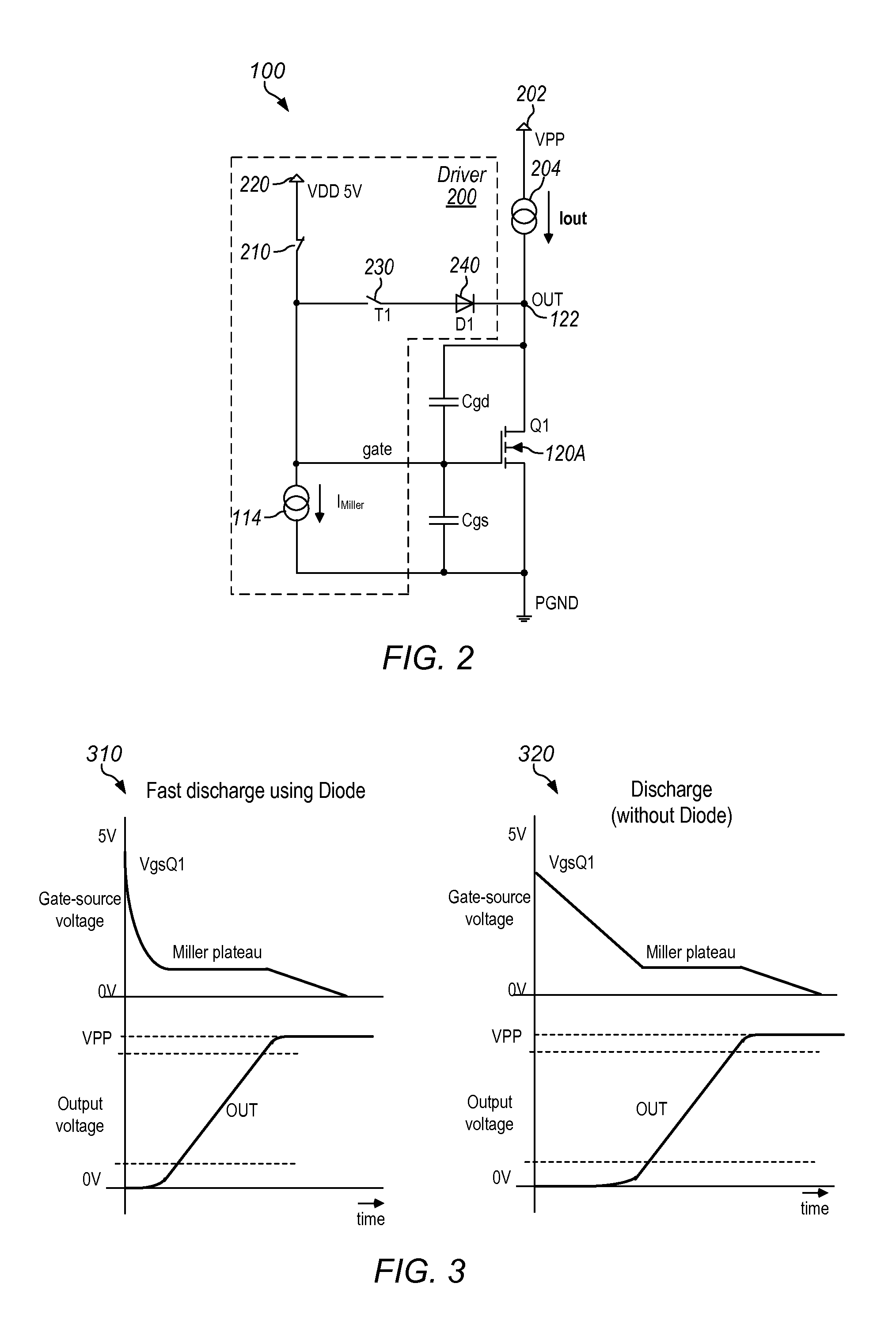
[0012]In one embodiment, an apparatus is disclosed that includes a first driver configured to discharge a gate of a first transistor. The first driver is configured to discharge the gate at a first rate until reaching a Miller plateau for the first transistor. The first driver is configured to discharge the gate at a second rate after reaching the Miller plateau. In such an embodiment, the first rate is greater than the second rate.

[0013]In another embodiment, a method is disclosed. The method includes a driver of an amplifier discharging a gate of a transistor at a first rate until reaching a Miller plateau for the transistor. The method further includes the driver discharging the gate at a second rate after reaching the Miller plateau. In such an embodiment, the first rate is greater than the second rate.

[...


PUM


Abstract

Techniques are disclosed relating to charging and discharging a gate of transistor. In one embodiment, an apparatus is disclosed that includes a driver configured to discharge a gate of a transistor. The driver is configured to discharge the gate at a first rate until reaching a Miller plateau for the transistor, and to discharge the gate at a second rate after reaching the Miller plateau. In such an embodiment, the first rate is greater than the second rate. In some embodiments, the driver is also configured to charge the gate of the transistor at a third rate until reaching a Miller plateau for the transistor, and to charge the gate at a fourth rate after reaching the Miller plateau, the third rate being greater than the fourth rate. In some embodiments, the apparatus is a class D amplifier.

Description

BACKGROUND[0001]1. Technical Field[0002]This disclosure relates generally to integrated circuits, and, more specifically, to controlling transistors in amplifier circuits.[0003]2. Description of the Related Art[0004]Developers may consider a variety of design objectives when creating an amplifier (such as a class D amplifier). Some objectives may include:[0005]1. Adjustable pulse-width modulation (PWM) output edge dV / dt to mitigate electromagnetic interference (EMI) by decreasing dV / dt;[0006]2. Small propagation delay variation with load current to reduce total harmonic distortion (THD);[0007]3. Propagation delay linearly dependant on load current to reduce THD;[0008]4. Small absolute value of propagation delay for a higher usable modulation index and better total harmonic distortion plus noise (THD+N) performance of a potential feedback loop;[0009]5. Minimum shoot-through current for better efficiency and to lower on-chip heat dissipation; and[0010]6. Minimum dead time to reduce TH...

Claims


Application Information

Patent Timeline
Patent Type & Authority Patents(United States)
IPC IPC(8): H03F3/217
CPCH03K7/08H03F3/2173H03K17/166H03K2217/0027H03K2217/0045
Inventor KONECNY, PAVELXIAO, JINWENKHOURY, JOHN M.
Owner SILICON LAB INC
Why Eureka
Try Eureka