
Method and system for efficient tracing and profiling of memory accesses during program execution

a memory access and program execution technology, applied in the field of microprocessors, can solve the problems of increasing the difficulty of collecting complete execution traces for applications, improving the efficiency of programs such as memory leakage, and reducing the accuracy of tracing and profiling, so as to reduce false positives, reduce unnecessary instrumentation, and increase system performance

Active Publication Date: 2013-07-02
ORACLE INT CORP
View PDF62 Cites 23 Cited by
  • Summary
  • Abstract
  • Description
  • Claims
  • Application Information

AI Technical Summary

Benefits of technology

This approach enhances system performance by minimizing unnecessary instrumentation and memory checking, thereby reducing execution time and false positives, allowing for more efficient memory profiling and error detection.

Problems solved by technology

Inefficient portions of the program such as memory leaks may be improved once the inefficiencies are known.
Without tools to efficiently identify expensive program portions such as memory leaks or errors, it is difficult to improve the performance of software.
Further, as processor speeds have increased, it has become more difficult to collect complete execution traces for applications.
This is in part due to the sheer number of instructions in such a trace, and also in part due to the performance overhead required to capture these traces.
However, instrumentation code brings performance overhead.
Straightforward instrumentation of each memory access operation may negatively affect run-time performance of the application.
With a straightforward instrumentation, it may take days or even weeks to perform memory profiling.

Method used


Image

  • Method and system for efficient tracing and profiling of memory accesses during program execution
  • Method and system for efficient tracing and profiling of memory accesses during program execution
  • Method and system for efficient tracing and profiling of memory accesses during program execution

Examples


Embodiment Construction

[0016]In the following description, numerous specific details are set forth to provide a thorough understanding of the present invention. However, one having ordinary skill in the art should recognize that the invention may be practiced without these specific details. In some instances, well-known circuits, structures, and techniques have not been shown in detail to avoid obscuring the present invention.

[0017]Referring to FIG. 1, one embodiment of a multi-core microprocessor 100 is shown. Microprocessor 100 may have multiple cores 102a-102d. As used herein, elements referred to by a reference numeral followed by a letter may be collectively referred to by the numeral alone. For example, cores 102a-102d may be collectively referred to as cores 102. Each core 102 may include a superscalar microarchitecture with one or more multi-stage pipelines. Each core 102 may be configured to execute instructions of software applications corresponding to an instruction set architecture (ISA) such ...


PUM


Abstract

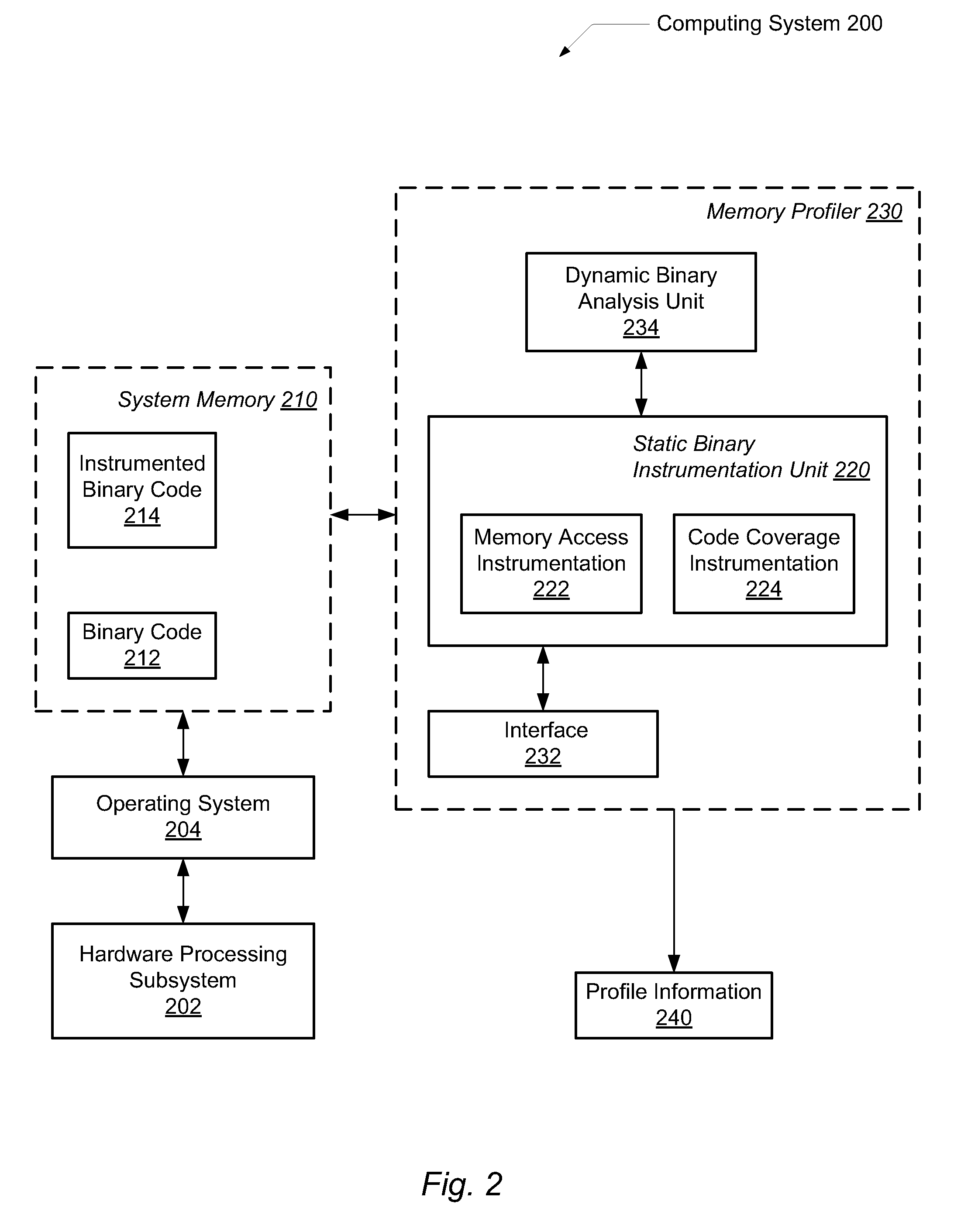
A system and method for performing efficient program instrumentation for memory profiling. A computing system comprises a memory profiler comprising a static binary instrumentation (SBI) tool and a dynamic binary analysis (DBA) tool. The profiler is configured to selectively instrument memory access operations of a software application. Instrumentation may be bypassed completely for an instruction if the instruction satisfies some predetermined conditions. Some sample conditions include the instruction accesses an address within a predetermined read-only area, the instruction accesses an address within a user-specified address range, and / or the instruction is a load instruction accessing a memory location determined from a data flow graph to store an initialized value. An instrumented memory access instruction may have memory checking analysis performed only upon an initial execution of the instruction in response to determining during initial execution that a read data value of the instruction is initialized. Both unnecessary instrumentation and memory checking analysis may be reduced.

Description

BACKGROUND OF THE INVENTION[0001]1. Field of the Invention[0002]This invention relates to microprocessors, and more particularly, to maintaining and performing efficient program instrumentation for memory profiling.[0003]2. Description of the Relevant Art[0004]Software programmers write applications to perform work according to an algorithm or a method. The program's performance may be increased based on an understanding of the dynamic behavior such as a memory profile of the entire program. Inefficient portions of the program such as memory leaks may be improved once the inefficiencies are known. In addition, understanding a program's dynamic behavior may be useful in computer architecture research, compiler research, or other. Such research may focus on trace generation, branch prediction techniques, cache memory subsystem modeling, fault tolerance studies, or other. Generally speaking, what is needed is a single, compact description of a program's entire control flow including lo...

Claims


Application Information

Patent Timeline
Patent Type & Authority Patents(United States)
IPC IPC(8): G06F12/00
CPCG06F11/3471G06F2201/865G06F12/0802G06F12/1441
Inventor PANCHENKO, MAKSIM V.GARUD, CHANDRASHEKHAR R.WANG, FU-HWA
Owner ORACLE INT CORP
Learn More