
Power supply device

a power supply device and power supply technology, applied in the direction of motor/generator/converter stopper, electronic commutator, dynamo-electric converter control, etc., can solve the problem of high improbability of intermediate-circuit short, and achieve low requirements, improved availability of power supply devices, and high power levels

Active Publication Date: 2013-07-02
SIEMENS AG
View PDF14 Cites 14 Cited by
  • Summary
  • Abstract
  • Description
  • Claims
  • Application Information

AI Technical Summary

Benefits of technology

The power supply device described in this patent is a new type of power converter that is suitable for use underwater and in other extreme environments. It uses distributed energy stores instead of a central energy store, which makes it more flexible and enables it to be placed much closer to the load being driven. The design of the intermediate circuit and lack of a specific short-circuit current also means that the converter valves do not need to be designed for a low-impedance short-circuit. The use of redundant subsystems and the avoidance of high motor voltage requirements and high currents make it easier to design and use motors for underwater use. The signal electronics for controlling the load-side power converter can also be placed on land or on a platform, which reduces complexity for encapsulation. Overall, this new power supply device offers improved flexibility, reduced complexity, and reduced cost for multiple-motor drives.

Problems solved by technology

Because of the design of the intermediate circuit, which does not necessarily have a lower inductance, and because of the lack of the intermediate-circuit capacitor, an intermediate-circuit short is highly improbable in comparison to the situation in a voltage intermediate-circuit converter with an intermediate-circuit capacitor.

Method used


Image

  • Power supply device
  • Power supply device
  • Power supply device

Examples


Embodiment Construction

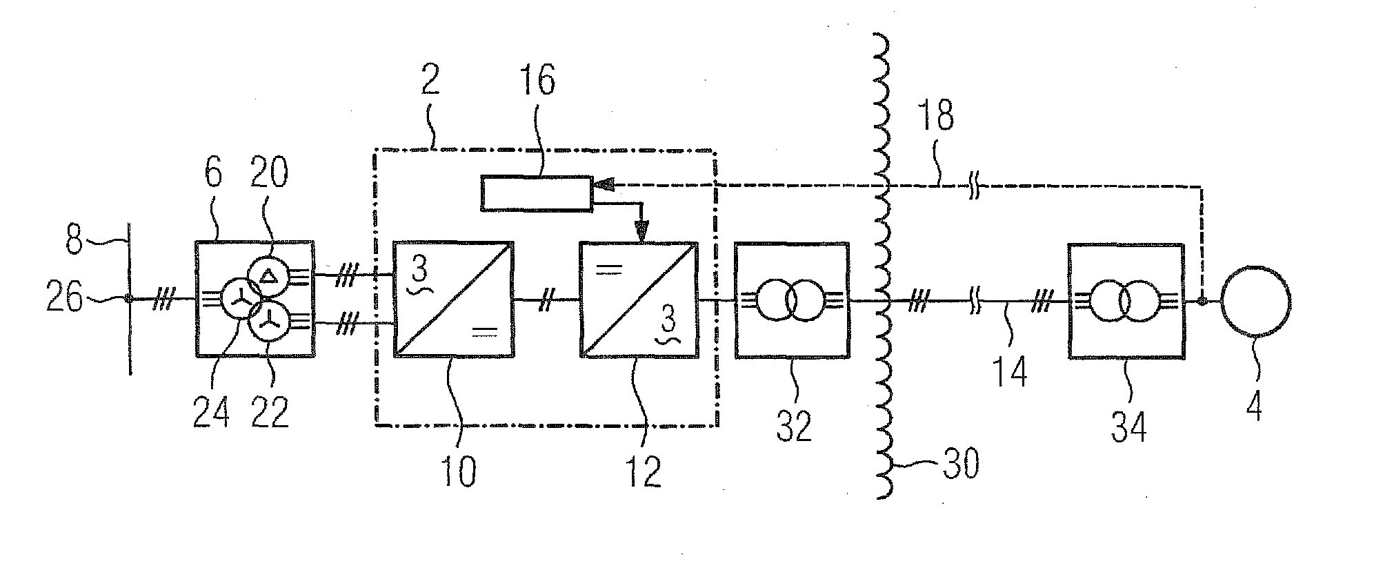
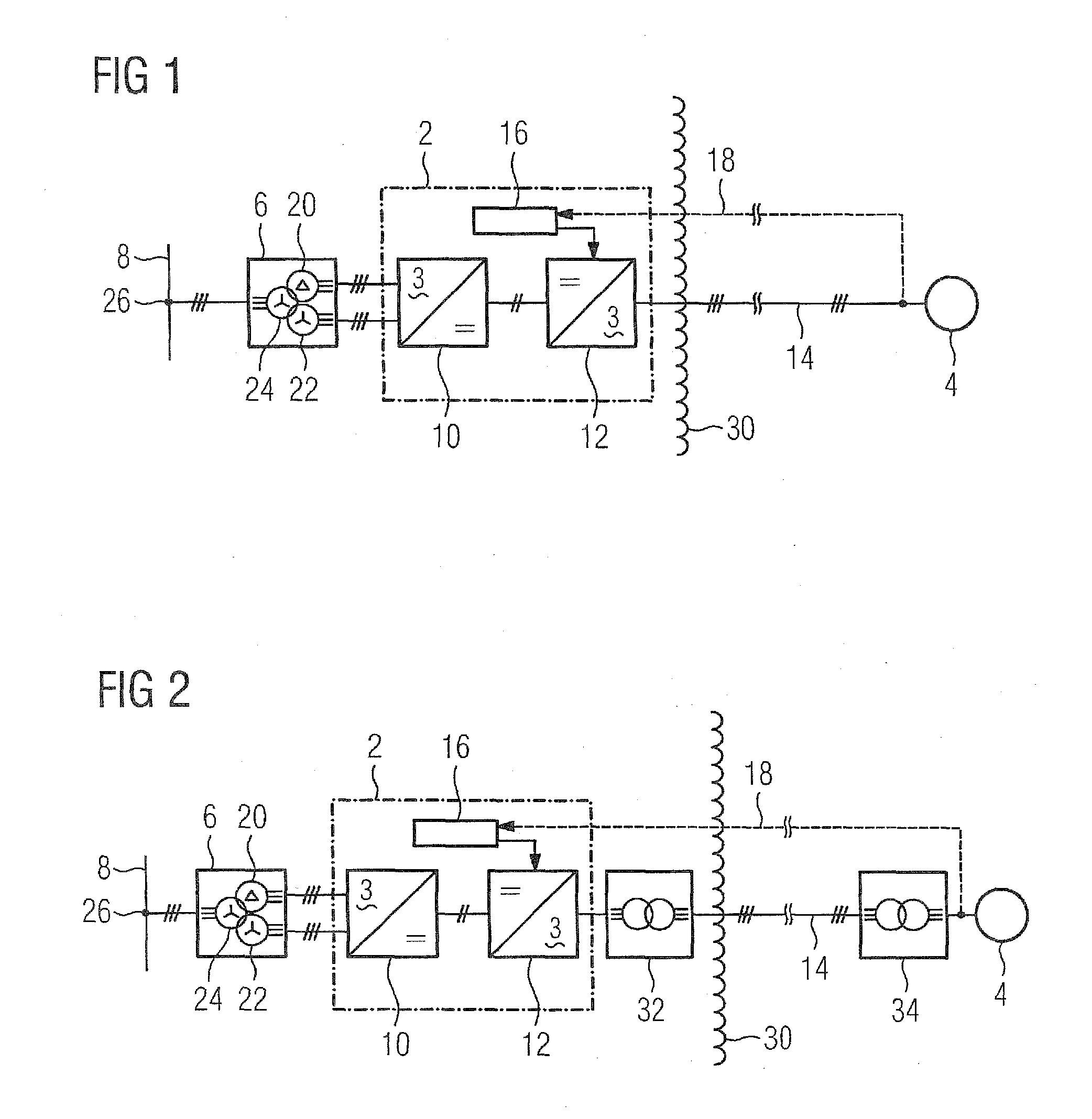
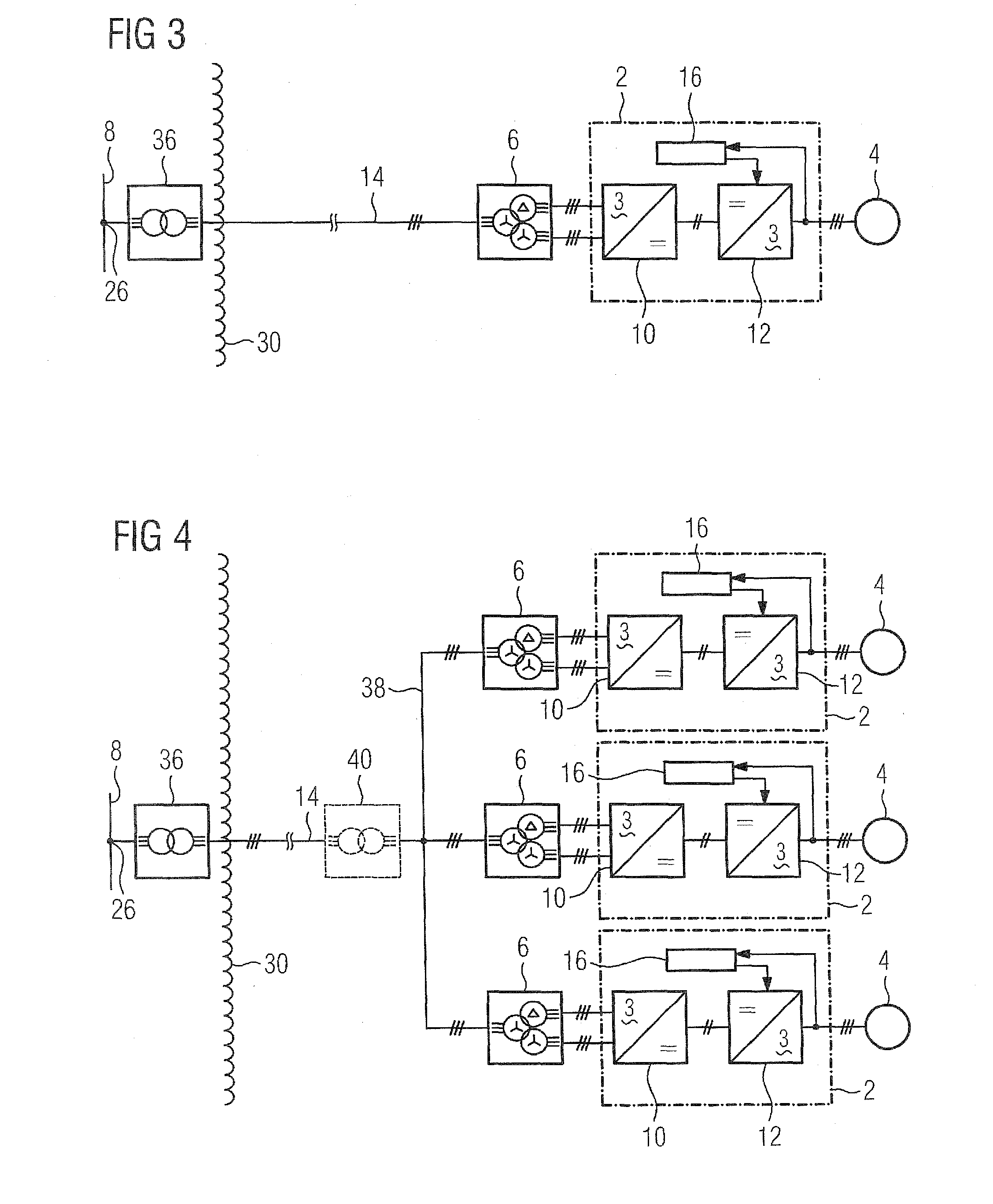
[0030]FIG. 5 schematically illustrates a first variant of the power supply device according to the invention. In this figure, 42 denotes a load-side power converter with distributed energy stores, 44 denotes a direct-current cable, and 46 denotes a control unit. The power converter 10 on the power supply system side and the power converter 42 on the load side are linked to one another on the DC voltage side by means of the direct-current cable 44. The control unit 46 of this load-side power converter 42 with distributed energy stores is connected by means of a data cable 18 to the signal electronics 16 in the power supply device, which is associated with the power converter 10 on the power supply system side. The power converter 10 on the power supply system side, which is in the form of an uncontrolled power converter, is linked on the AC voltage side by means of the power supply system transformer 36 to the feed point 26 of the feeding power supply system 8. In the power supply de...


PUM


Abstract

A power supply device for a variable rotation speed drive includes a free-running converter connected to a land-based power grid, and an inverter connected to the variable rotation speed drive. A direct-current cable electrically connects the DC side of the converter with the DC side of the inverter. The inverter includes a plurality of phase modules having an upper and a lower valve branches with least two series-connected, two-pole subsystems with distributed energy storage devices. The inverter is located on the seabed in immediate vicinity of the variable rotation speed drive. Signal electronics of the inverter is located on land. In this way, the distance between the power supply on land and the drive on the ocean floor can reach several hundred kilometers, with ocean depths of several kilometers.

Description

CROSS-REFERENCES TO RELATED APPLICATIONS[0001]This application is the U.S. National Stage of International Application No. PCT / EP2009 / 053654, filed Mar. 27, 2009, which designated the United States and has been published as International Publication No. WO 2009 / 135730, and which claims the priority of German Patent Application, Serial No. 10 2008 022 618.1, filed May 7, 2008, pursuant to 35 U.S.C. 119(a)-(d).BACKGROUND OF THE INVENTION[0002]The invention relates to a power supply device for a variable rotation speed drive which is arranged on the seabed.[0003]Variable rotation speed drives, consisting of an electric motor and a pump or a compressor, are supplied by means of a power supply device such as this, when on the seabed, with power from an electrical power supply system on land. The distance between the feeder on land and the drive on the seabed may be several hundred kilometers, at sea depths of several kilometers.[0004]Variable rotation speed drives for underwater applicat...

Claims


Application Information

Patent Timeline
IPC IPC(8): H02P27/06H02P6/00
CPCH02M7/483H02P6/001H02M2007/4835H02M7/4835
Inventor BLOCHER, BERNDHILLER, MARCSOMMER, RAINER
Owner SIEMENS AG
Learn More