Multilayered electrochemical energy storage device and method of manufacture thereof

a multi-layered electrochemical and energy storage technology, applied in the manufacture of secondary cells, cell components, cell component details, etc., can solve the problems of cumbersome construction, large width of multi-layered structure, and difficulty in sealing and packaging such cell stacks

Inactive Publication Date: 2013-06-25
CELLERGY
View PDF13 Cites 3 Cited by
  • Summary
  • Abstract
  • Description
  • Claims
  • Application Information

AI Technical Summary

Benefits of technology

[0012]The terms “separator” or “separating medium” are interchangeably used herein to describe all thin porous films or membranes commonly used to electronically separate between electrodes in an electrochemical cell. It has now been found that it is possible to seal the pores of the separator in the peripheral region thereof, forming one or more non-sealed regions thereon according to a desired pattern, and then to directly print electrodes onto said one or more non-sealed regions of the separator. The resultant construct, namely, a separator having one or more electrodes printed thereon, such that each electrode is surrounded by a sealed region of the separator, may be effectively used in the preparation of multilayered structures that may serve, inter alia, as bi-polar electrochemical capacitors.
[0014]The term “sealed” is used to indicate that the region is non-permeable to the electrolyte contained in the electrode; the sealed region surrounding the electrode printed on the separator prevents the seepage of the electrolyte from the electrode to the circumferential region of the cell. According to one preferred embodiment, the sealed peripheral region of the separator, which surrounds the electrode printed thereon, is impregnated with an electrically non-conductive material, preferably an adhesive, which blocks the pores of the separator in said region and also allows the attachment of the separator to the current collectors.
[0020]The multilayered structure obtained by the method described above is a spatial body, typically having a shape of a rectangular parallelepiped. The height of this body is determined by the number of the vertically aligned layers (the n+1 current collectors and the n separators). The number of the individual energy storage devices that may be isolated from the multilayered structure depends on the number of discrete electrodes distributed on the surface of the n current collectors and the corresponding number of discrete electrodes printed on the surface of the separators. Thus, a plurality of individual energy storage devices, each of which comprises n vertically aligned cells, may be conveniently isolated from the multilayered structure by scissors, cutter, knife, or other mechanical means.

Problems solved by technology

This construction is cumbersome due to this electrode arrangement wherein two electrodes are provided on the two sides of each internal current collector of the bipolar energy storage device.
Moreover, the sealing and packaging of such cell stacks is not a simple task and the width of their multilayered structure is relatively large.

Method used


Image

  • Multilayered electrochemical energy storage device and method of manufacture thereof
  • Multilayered electrochemical energy storage device and method of manufacture thereof
  • Multilayered electrochemical energy storage device and method of manufacture thereof

Examples


Embodiment Construction

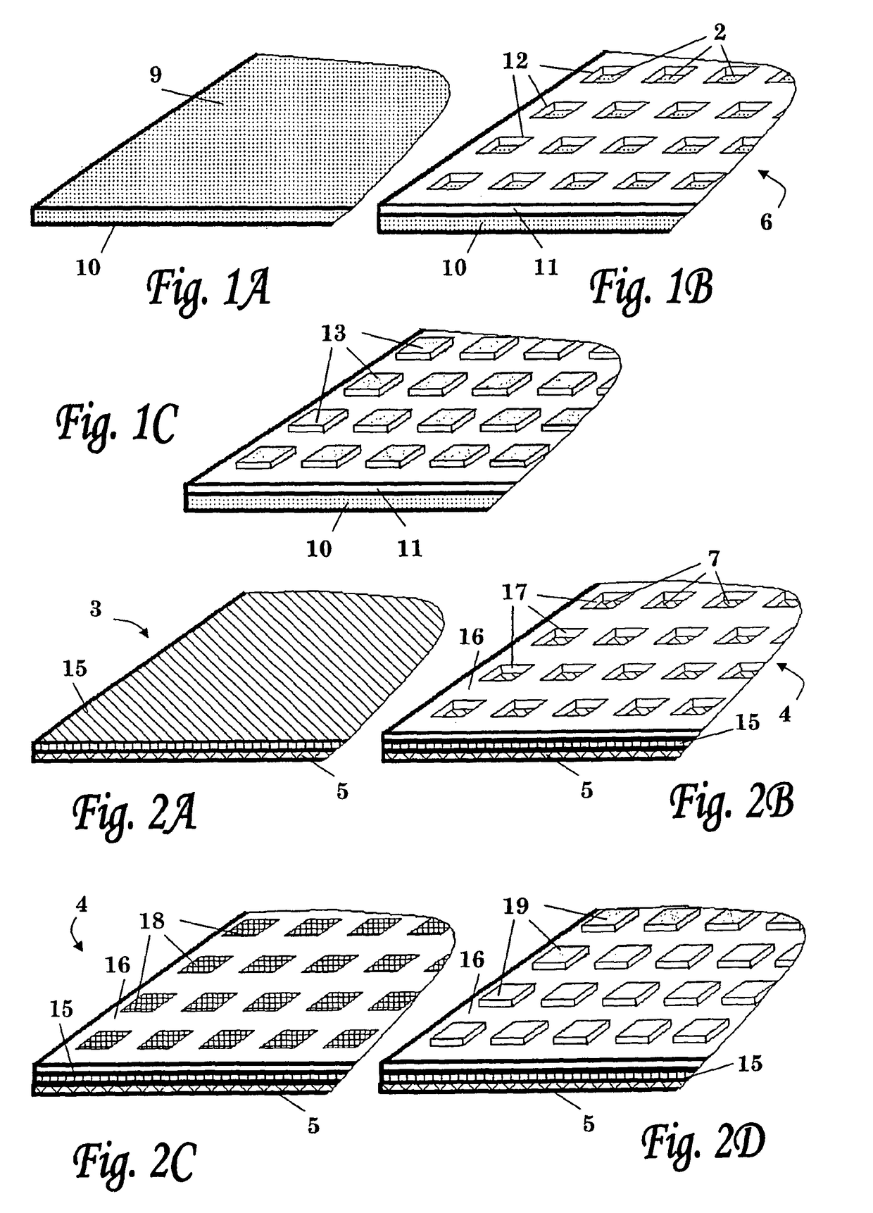
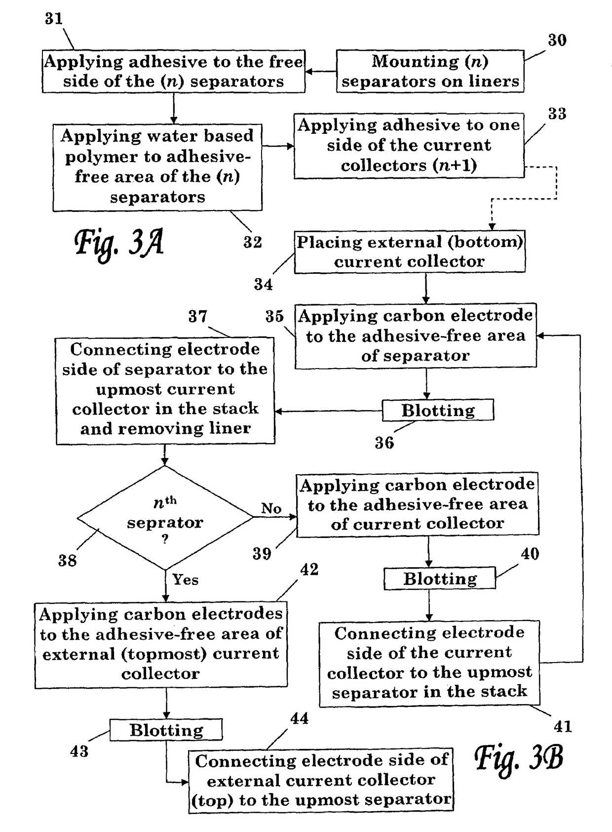
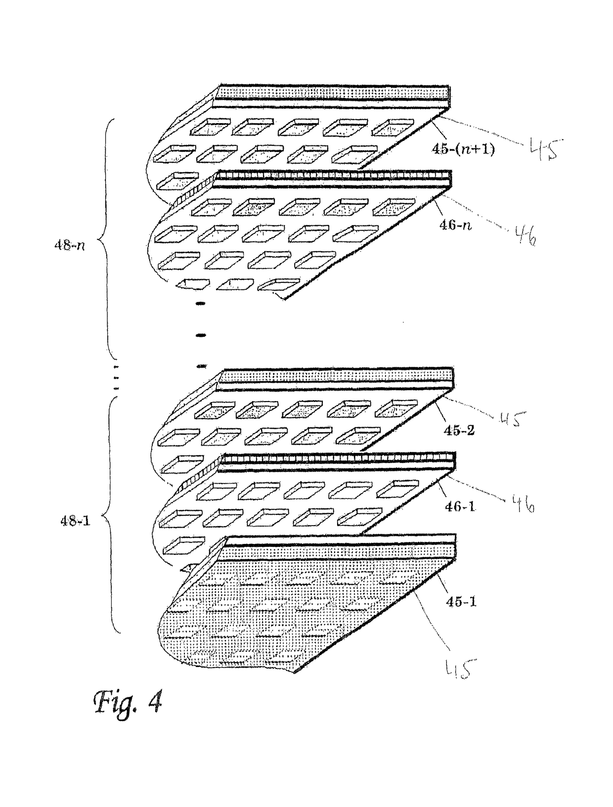
[0031]The present invention is directed to a multilayered energy storage device and to a method of its manufacture. More particularly, the present invention is directed to a bipolar capacitor constructed from a stack of n+1 current collectors and n separators disposed therebetween, wherein an electrode is attached to n current collectors and n separators (wherein n is an integer, n>=1) of the stack.

[0032]Current collectors to be used according to the present invention are made of a conductive material that is chemically inert to the aqueous electrolyte contained in the electrode. The current collector may be provided in the form of a metal foil, such as aluminum foil, plated metal or metal coated with a protective oxide. Alternatively, the current collector is a polymeric or a co-polymeric sheet, such as polyethylene or polytetrafluoroethane (Teflon), rubber or PVC (polyvinylchloride) loaded with conductive particles such as carbon black, graphite, metallic or plated metallic partic...


PUM

PropertyMeasurementUnit
thicknessaaaaaaaaaa
thickaaaaaaaaaa
thickaaaaaaaaaa

Abstract

An energy storage device comprising one or more cells, wherein each cell is defined by a pair of electrodes and a separator placed therebetween, wherein each cell is bounded by two current collectors, the geometric form and size of said separator being identical to the form and size of said current collectors, and wherein in each cell, one electrode is printed on one of said two current collectors and the other electrode is printed on one face of the separator, the two electrodes being electronically insulated by means of said separator, and wherein the peripheral region of the separator, which surrounds the electrode printed thereon, is sealed.

Description

[0001]This application is the U.S. national phase of International Application No. PCT / IL2006 / 000870, filed 27 Jul. 2006, which designated the U.S. and claims priority to Israel Patent Application No. 169932, filed 27 Jul. 2005, the entire contents of each of which are hereby incorporated by reference.FIELD OF THE INVENTION[0002]The present invention relates to energy storage devices, and specifically, to a multilayered electrochemical energy storage devices and to a method for manufacturing the same. More particularly, the invention relates to a method for manufacturing multilayered electrochemical capacitors or batteries comprising printable electrodes.BACKGROUND OF THE INVENTION[0003]A single cell energy storage device typically consists of two conducting plates (hereinafter current collectors) and an electronically insulating layer (dielectric, hereinafter separator) disposed therebetween. Electrodes are usually disposed between the current collectors and the separator and a liq...

Claims


Application Information

Patent Timeline
Patent Type & Authority Patents(United States)
IPC IPC(8): H01G9/00H01M50/463
CPCH01G9/02H01G9/155H01M2/18H01M6/40H01M10/0436Y02E60/13H01M4/70Y02E60/10H01M50/463H01G11/28H01G11/52H01G11/80H01G11/12
Inventor LANG, JOEL
Owner CELLERGY
Why Eureka
Try Eureka