Electric precipitator and high voltage electrode thereof

a technology of electric precipitator and high voltage electrode, which is applied in the direction of discharge tube/lamp details, non-electron-emitting electrode materials, lamp incadescent bodies, etc., can solve the problems of increasing electric power consumption, requiring a large scale power supply to apply high voltage, and difficulty in reducing the width of the electric precipitator below a certain level, so as to reduce the width and reduce the electric power required to operate. , efficient use of space for installation

Active Publication Date: 2013-06-25
SAMSUNG ELECTRONICS CO LTD
View PDF17 Cites 12 Cited by
  • Summary
  • Abstract
  • Description
  • Claims
  • Application Information

AI Technical Summary

Benefits of technology

[0010]Therefore, it is an aspect of the invention to provide an electric precipitator fabricated with a considerably small width so as to more efficiently utilize a space for installation thereof.
[0023]Briefly, the electric precipitator according to an exemplary embodiment of the present invention includes the charging part to charge a pollutant on the high voltage electrode and the dust collection part to precipitate the charged pollutant, so that the electric precipitator has a considerably reduced width and therefore can more efficiently utilize space for installation thereof.
[0024]In addition, the electric precipitator according to the exemplary embodiment of the present invention has the first electrode layer for fabrication of the charging part, which is made of conductive fibers to generate a discharge even at a low voltage, so that a small scale power supply may be used and electric power required to operate the electric precipitator may be considerably reduced.

Problems solved by technology

However, in order to generate a discharge between an electric wire and a ground electrode, such a conventional electric precipitator requires a considerably high voltage to be applied to the discharge electrode, thus requiring a large scale power supply to apply high voltage and increasing electric power consumption.
Furthermore, since high voltage is applied to the discharge electrode as described above, the discharge electrode must be sufficiently spaced from the dust collection part in consideration of safety, and therefore, it is difficult to reduce a width of the electric precipitator below a certain level.

Method used


Image

  • Electric precipitator and high voltage electrode thereof
  • Electric precipitator and high voltage electrode thereof
  • Electric precipitator and high voltage electrode thereof

Examples


Embodiment Construction

[0033]Reference will now be made in detail to the embodiments, examples of which are illustrated in the accompanying drawings, wherein like reference numerals refer to the like elements throughout. The embodiments are described below to explain the present invention by referring to the figures.

[0034]An electric precipitator according to an exemplary embodiment of the present invention will be described in detail with reference to the accompanying drawings.

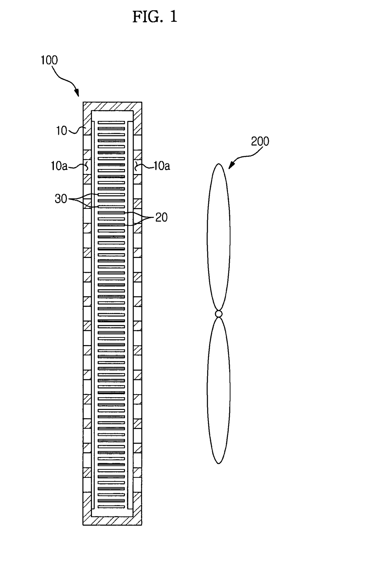
[0035]As shown in FIG. 1, an electric precipitator 100 according to the exemplary embodiment is a device for collection of foreign materials or pollutants such as dust contained in air, typically arranged on an air flow path through which the air flows by an air blowing fan 200. The electric precipitator 100 includes a frame 10 which constitutes an outer shape of the electric precipitator 100 and has grid type vent holes 10a provided at both sides thereof to pass air in a single direction through the vent holes; a plurality of high...


PUM


Abstract

An electrode precipitator having a high voltage electrode and a low voltage electrode arranged apart from each other at a desired interval. The high voltage electrode includes a charging part which is positioned upstream of an air flow direction to charge a pollutant, and a dust collection part which is spaced from the charging part and positioned downstream of the air flow direction to precipitate the charged pollutant therein.

Description

CROSS-REFERENCE TO RELATED APPLICATIONS[0001]This application claims the benefit of Korean Patent Application No. 2008-0126184, filed on Dec. 11, 2008 in the Korean Intellectual Property Office, the disclosure of which is incorporated herein by reference.BACKGROUND[0002]1. Field[0003]Embodiments of the present invention relate to an electric precipitator for collection of foreign materials or pollutants such as dust by electric attraction.[0004]2. Description of the Related Art[0005]An electric precipitator is generally mounted on an air conditioner. More particularly, the electric precipitator is arranged on an air flow path to collect foreign materials or pollutants such as dust (hereinafter, referred to as ‘pollutant’) contained in air passing through the electric precipitator by electric attraction.[0006]A conventional electric precipitator generally has a double-stage type structure to precipitate a pollutant, including a charging part which is positioned upstream of an air flo...

Claims


Application Information

Patent Timeline
Patent Type & Authority Patents(United States)
IPC IPC(8): B03C3/40
CPCB03C3/08B03C3/64B03C3/47
Inventor JI, JUN HOYASUHIKO, KOCHIYAMANOH, HYONG SOOYUN, SO YOUNGCHO, HAN WOOK
Owner SAMSUNG ELECTRONICS CO LTD
Why Eureka
Try Eureka