
Sensing device using proximity sensor and mobile terminal having the same

a technology of proximity sensor and sensing device, which is applied in the direction of optical radiation measurement, pulse technique, instruments, etc., can solve the problem that the touch screen may often malfunction

Active Publication Date: 2013-05-28
SAMSUNG ELECTRONICS CO LTD
View PDF9 Cites 47 Cited by
  • Summary
  • Abstract
  • Description
  • Claims
  • Application Information

AI Technical Summary

Benefits of technology

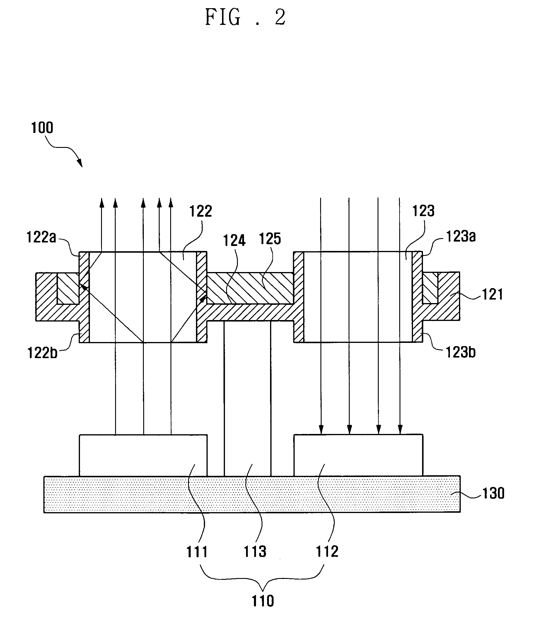
The present invention is a sensing device using a proximity sensor and a mobile terminal including the same. This invention prevents malfunctions of the proximity sensor and accurately detects the approach of an external object through an opaque reflective film formed in the transparent lens body of the lens unit installed on the proximity sensor. The lens body and the reflective film are integrally formed with each other by double injection molding, simplifying the manufacturing process and reducing manufacturing costs. The light emitting unit of the proximity sensor emits light with maximum power, increasing the sensing distance and reducing power consumption when the object approaches at the same distance from the proximity sensor. The mobile terminal is also covered with through-openings to prevent exposure of the inside of the mobile terminal to the outside.

Problems solved by technology

In the mobile terminal including the touch screen, when the user puts the mobile terminal to his / her ear to talk, the ear or cheek of the user presses the touch screen of the mobile terminal so that the touch screen may often malfunction.
Because the plane lens and the glass sheet are made of transparent materials, light emitted from the proximity sensor is diffusively reflected from the surface or the inside of the plane lens and the glass sheet so that the proximity sensor malfunctions and erroneously senses the diffused reflection as the ear or cheek of the user approaching the touch screen.

Method used


Image

  • Sensing device using proximity sensor and mobile terminal having the same
  • Sensing device using proximity sensor and mobile terminal having the same
  • Sensing device using proximity sensor and mobile terminal having the same

Examples


Embodiment Construction

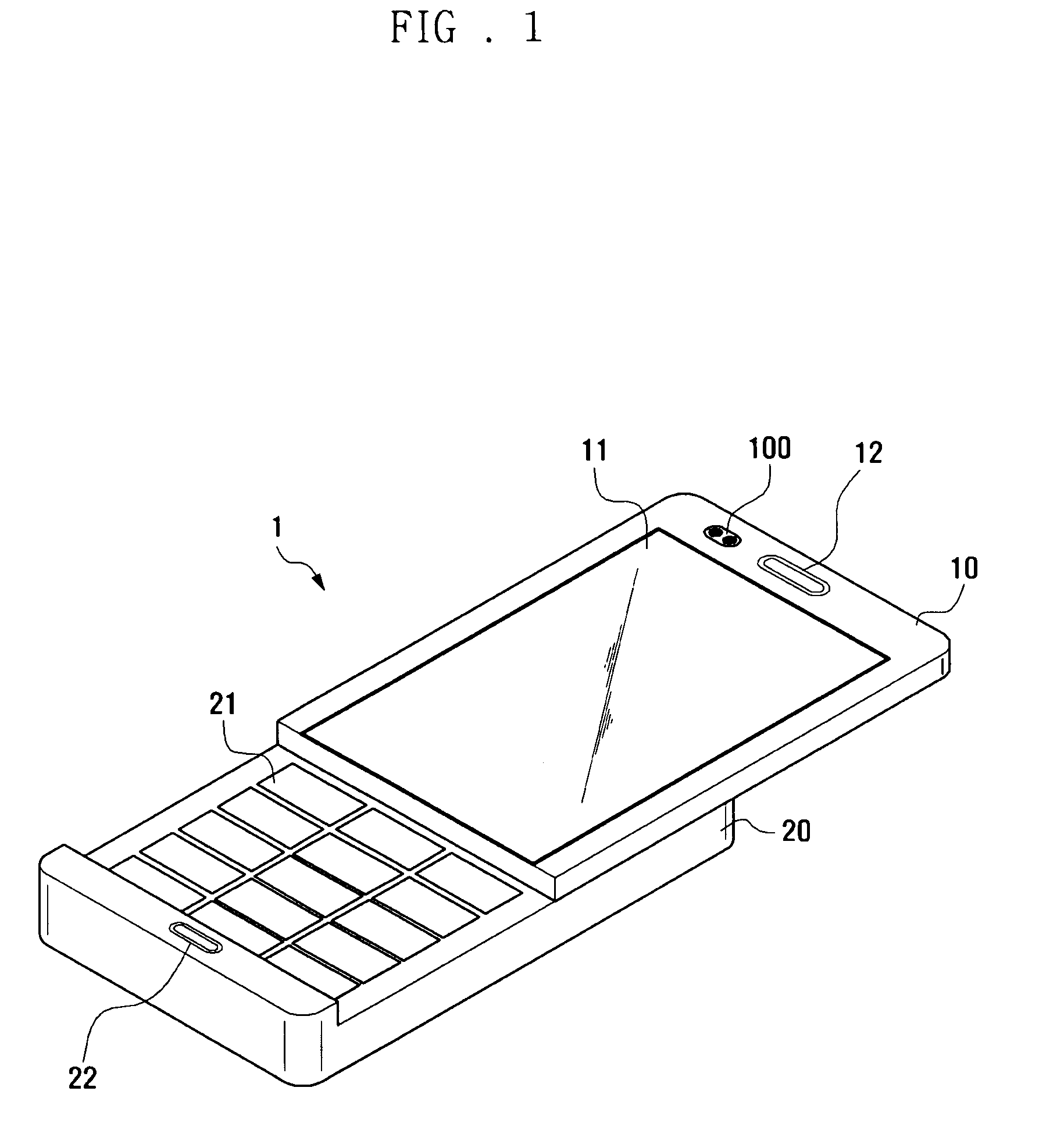
[0027]FIGS. 1 through 6B, discussed below, and the various embodiments used to describe the principles of the present disclosure in this patent document are by way of illustration only and should not be construed in any way to limit the scope of the disclosure.

[0028]Those skilled in the art will understand that the principles of the present disclosure may be implemented in any suitably arranged system.

[0029]In the same manner, some elements are exaggerated, omitted, and / or schematically depicted in the drawings. Moreover, sizes of respective elements are different from actual sizes thereof. The same reference symbols are used throughout the drawings to refer to the same or like parts.

[0030]Hereinafter, a sensing device using a proximity sensor and a mobile terminal including the same according to exemplary embodiments of the present invention will be described with reference to the accompanying drawings.

[0031]For the purpose of description, a mobile communication terminal is describ...


PUM


Abstract

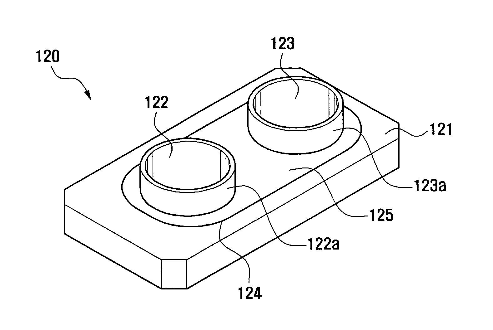
A mobile terminal includes a sensing device that uses a proximity sensor. The sensing device includes: a proximity sensor sensing approach of an external object; and a lens unit installed on top of the proximity sensor. The lens unit includes: a lens body having a first through-opening through which light emitted from a light emitting unit of the proximity sensor passes and a second through-opening through which light, reflected from the external object and entering into a light receiving unit of the proximity sensor, passes; and a reflective film formed in the lens body to surround edges of the first through-opening and the second through-opening. The lens body and the reflective film are integrated with each other by double injection molding. The lens body and the reflecting film are manufactured in a single body by double injection molding.

Description

CROSS-REFERENCE TO RELATED APPLICATION(S) AND CLAIM OF PRIORITY[0001]The present application is related to and claims priority to an application entitled “SENSING DEVICE USING PROXIMITY SENSOR AND MOBILE TERMINAL HAVING THE SAME” filed in the Korean Intellectual Property Office on Jan. 5, 2009 and assigned Serial No. 10-2009-0000313, the contents of which are incorporated herein by reference.TECHNICAL FIELD OF THE INVENTION[0002]The present invention relates generally to a sensing device using a proximity sensor and a mobile terminal having the same and, more particularly, to a sensing device using a proximity sensor in which malfunction of the proximity sensor is prevented and a mobile terminal having the same.BACKGROUND OF THE INVENTION[0003]Generally, a mobile terminal is an electronic device that allows a user to perform wireless communication, access a network, receive a digital broadcast, and so forth, regardless of time and place. Recently, mobile terminals have been develope...

Claims


Application Information

Patent Timeline
Patent Type & Authority Patents(United States)
IPC IPC(8): H01J40/14G06M7/00H04N7/18H01H35/00H04M1/02H04M1/21
CPCH03K17/941H03K2217/94108H04M1/605H04M2250/12G01B11/00G01J1/02H04B1/38
Inventor YUN, SANG WON
Owner SAMSUNG ELECTRONICS CO LTD
Learn More