
Urea-based mixing process for increasing combustion efficiency and reduction of nitrogen oxides (NOx)

a technology of nitrogen oxides and mixing processes, applied in the field of system and method for improving the efficiency of combustion reactions and reducing pollutants, can solve the problems of not optimizing the combustion efficiency or furnace heat exchange efficiency of the nox reduction system, and achieve the effect of reducing the formation of nox

Inactive Publication Date: 2013-05-28
THE POWER IND GRP
View PDF110 Cites 7 Cited by
  • Summary
  • Abstract
  • Description
  • Claims
  • Application Information

AI Technical Summary

Benefits of technology

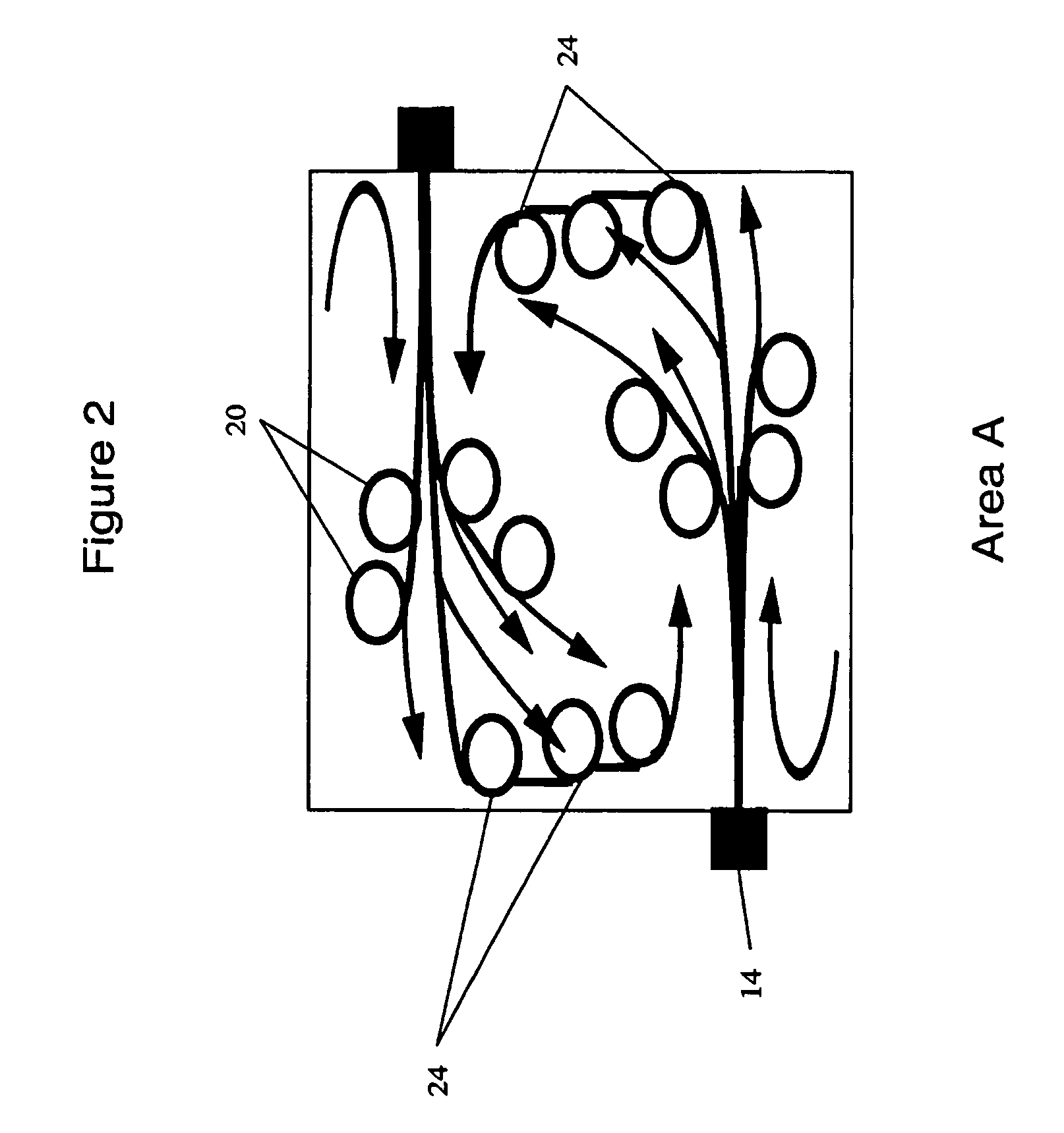
[0011]Thus, it is one aspect of the present invention to reduce NOx formation by the asymmetric injection of urea solutions at temperatures above 2050 F. with use of high-velocity secondary air for the induction of turbulence in the gas column.

Problems solved by technology

However, these existing NOx reduction systems do not optimize combustion efficiency or furnace heat exchange efficiency.

Method used


Image

  • Urea-based mixing process for increasing combustion efficiency and reduction of nitrogen oxides (NOx)
  • Urea-based mixing process for increasing combustion efficiency and reduction of nitrogen oxides (NOx)
  • Urea-based mixing process for increasing combustion efficiency and reduction of nitrogen oxides (NOx)

Examples


Embodiment Construction

[0022]In the following description, like reference characters designate like or corresponding parts throughout the several views. Also in the following description, it is to be understood that such terms as “forward,”“rearward,”“front,”“back,”“right,”“left,”“upwardly,”“downwardly,” and the like are words of convenience and are not to be construed as limiting terms. In this description of the embodiment, the term “duct” is used to describe a reagent injection passageway without any constriction on the end. The term “injector” is used to describe a reagent injection passageway with a constrictive orifice on the end. The orifice can be a hole or a nozzle. An injection device is a device that incorporates ducts or injectors or both.

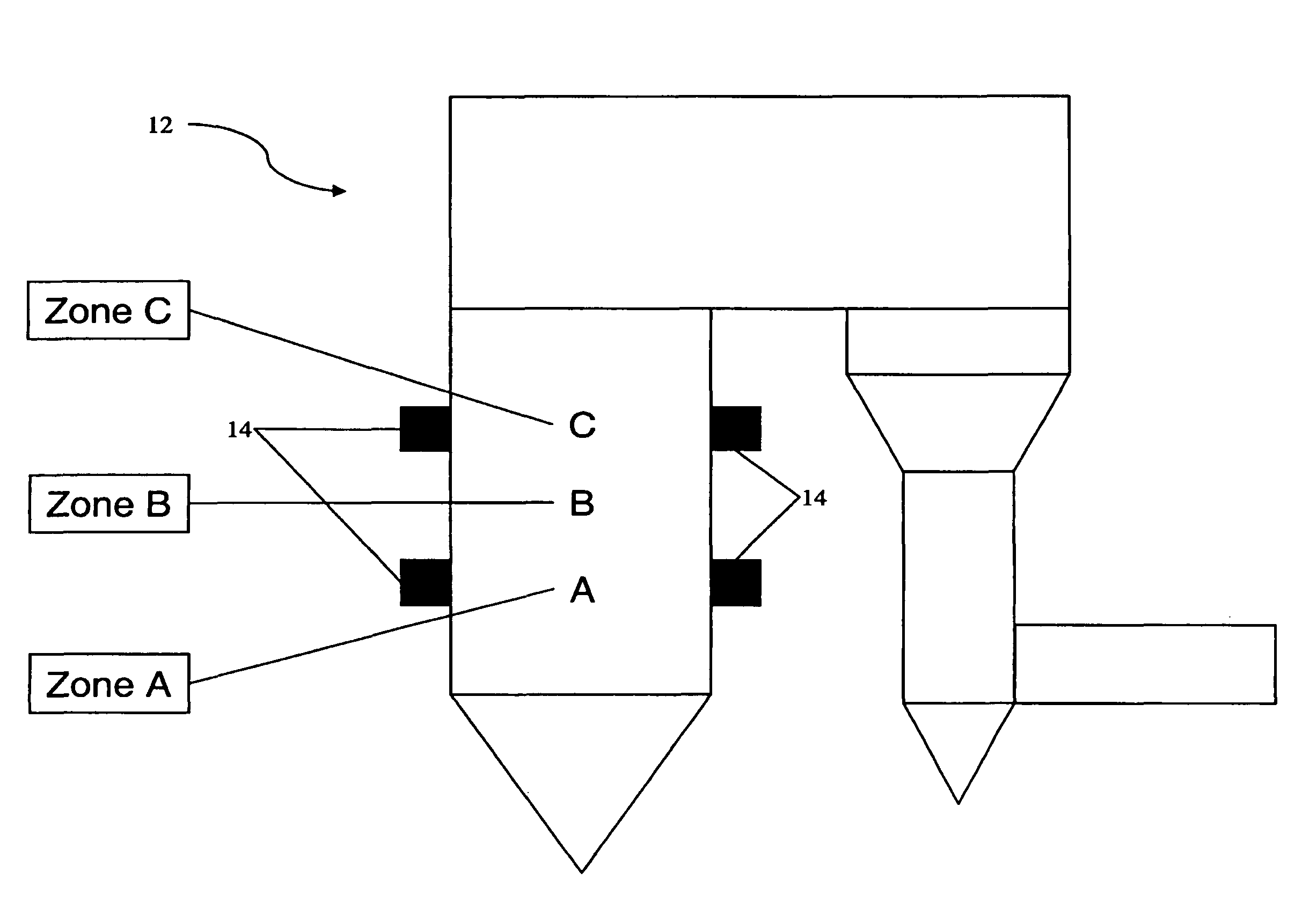
[0023]Referring now to the drawings in general, the illustrations are for the purpose of describing a preferred embodiment of the invention and are not intended to limit the invention thereto. Shown in FIG. 1 is a side view of a combustion furnace, generally ...


PUM

PropertyMeasurementUnit
temperaturesaaaaaaaaaa
temperatureaaaaaaaaaa

Abstract

A method for reducing NOx formation, including the steps of: providing a furnace with a plurality of secondary air injection ducts, asymmetrically positioned in an opposing manner; injecting fuel with primary air through a first stage prior to injection of a second air; injecting secondary air and aqueous urea solution through the plurality of reagent injection ducts; controlling the asymmetrical injection to produce a high velocity mass flow and a turbulence resulting in dispersion of the urea solution into the combustion space, thereby providing reduced NOx formation in the combustion process.

Description

CROSS-REFERENCE TO RELATED APPLICATIONS[0001]This non-provisional utility patent application claims the benefit of one or more prior filed applications, with a reference to each such prior application as follows: the present application is a Continuation of U.S. Ser. No. 10 / 798,093 filed Mar. 11, 2004 now abandoned, which is a Continuation-In-Part of application Ser. Nos. 10 / 391,825 filed Mar. 19, 2003 now abandoned, 10 / 461,567 filed Jun. 13, 2003 now abandoned, and 10 / 742,260 filed Dec. 20, 2003, which are incorporated herein by reference in their entirety.BACKGROUND OF THE INVENTION[0002](1) Field of the Invention[0003]The present invention relates generally to a system and method for improving the efficiency of combustion reactions and for reducing pollutants, and, more particularly, to a system and method for improving combustion efficiency and reduction of nitrogen oxides (NOx) using nitrogenous agents.[0004](2) Description of the Prior Art[0005]Increases in fuel costs have req...

Claims


Application Information

Patent Timeline
Patent Type & Authority Patents(United States)
IPC IPC(8): F23D11/44
CPCF23C5/32F23J7/00F23L7/002F23L9/04
Inventor HIGGINS, BRIAN S.
Owner THE POWER IND GRP
Learn More