
Cartridge for a firearm

a cartridge and firearm technology, applied in the field of centerfire cartridges for rifles, can solve the problems of many extreme dimensional ratios, inability to meet the requirements of the intended use, and large constraints on the dimensions of the cartridg

Active Publication Date: 2013-05-21
HORNADY MFG CO
View PDF2 Cites 159 Cited by
  • Summary
  • Abstract
  • Description
  • Claims
  • Application Information

AI Technical Summary

Problems solved by technology

However, the variations are not infinite, and there are important constraints on cartridge dimensions.
First, the characteristics of gun powder and structural limitations on rifle actions (which define the chamber) make many extreme dimensional ratios impractical or unsafe.
There is very little that can be done after a case is made to change the dimensions near the case head in any useful manner, aside from minor (but impractical in large scale production) machining operations such as to trim the rim to a smaller rebated diameter or to machine turn off a belt.
While it is easy to conceive of cartridges outside of established families (those with established case head dimensions) there is a powerful economic barrier to creating new cartridges outside of these families, due to the large tooling cost for a new cartridge.
A third limitation on cartridge dimensions is the dimensions of the actions of the rifles that are to receive them.
Again, rifle actions may be conceived in any length or width, but it is impractical for rifle manufacturers to generate a new size for a new cartridge that may be proposed (and there is a powerful disincentive to develop a cartridge for which there are no rifles capable of shooting it—or if the only rifles that do receive it are needlessly heavy, large or expensive.)
While it is disadvantageous to employ an action that is significantly longer than needed for a given cartridge due to weight, cost, size, and strength reasons, slight excess length is tolerated.
In certain bins, the cartridges previously developed to fit the dimensional constraints have limitations on the power available to shooters.

Method used


Image

  • Cartridge for a firearm
  • Cartridge for a firearm
  • Cartridge for a firearm

Examples


Embodiment Construction

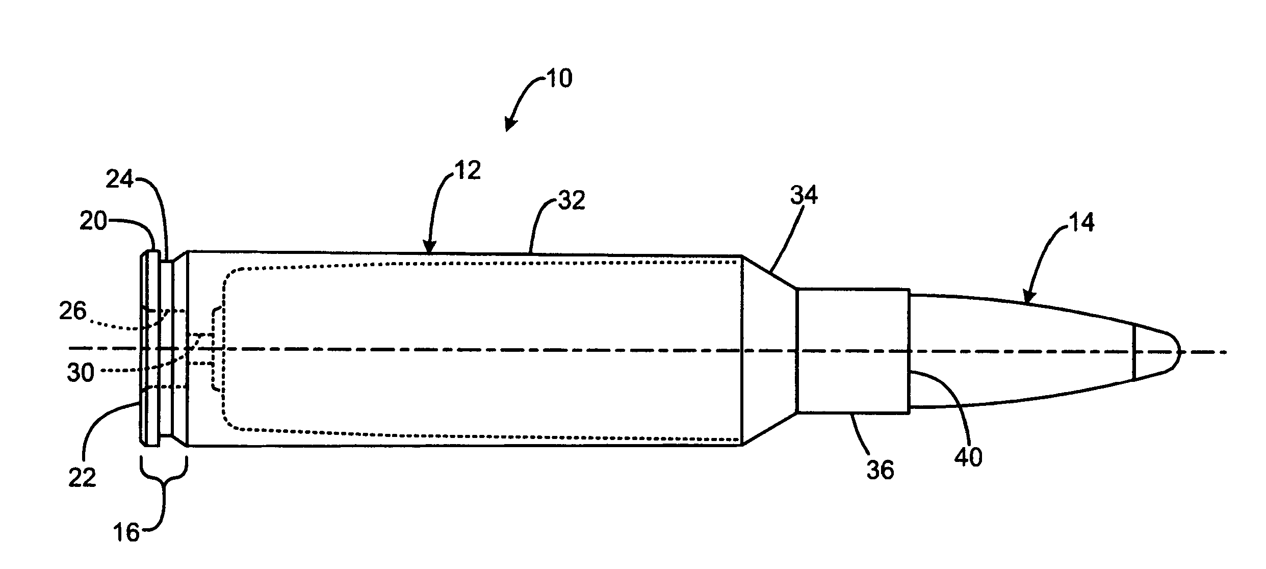
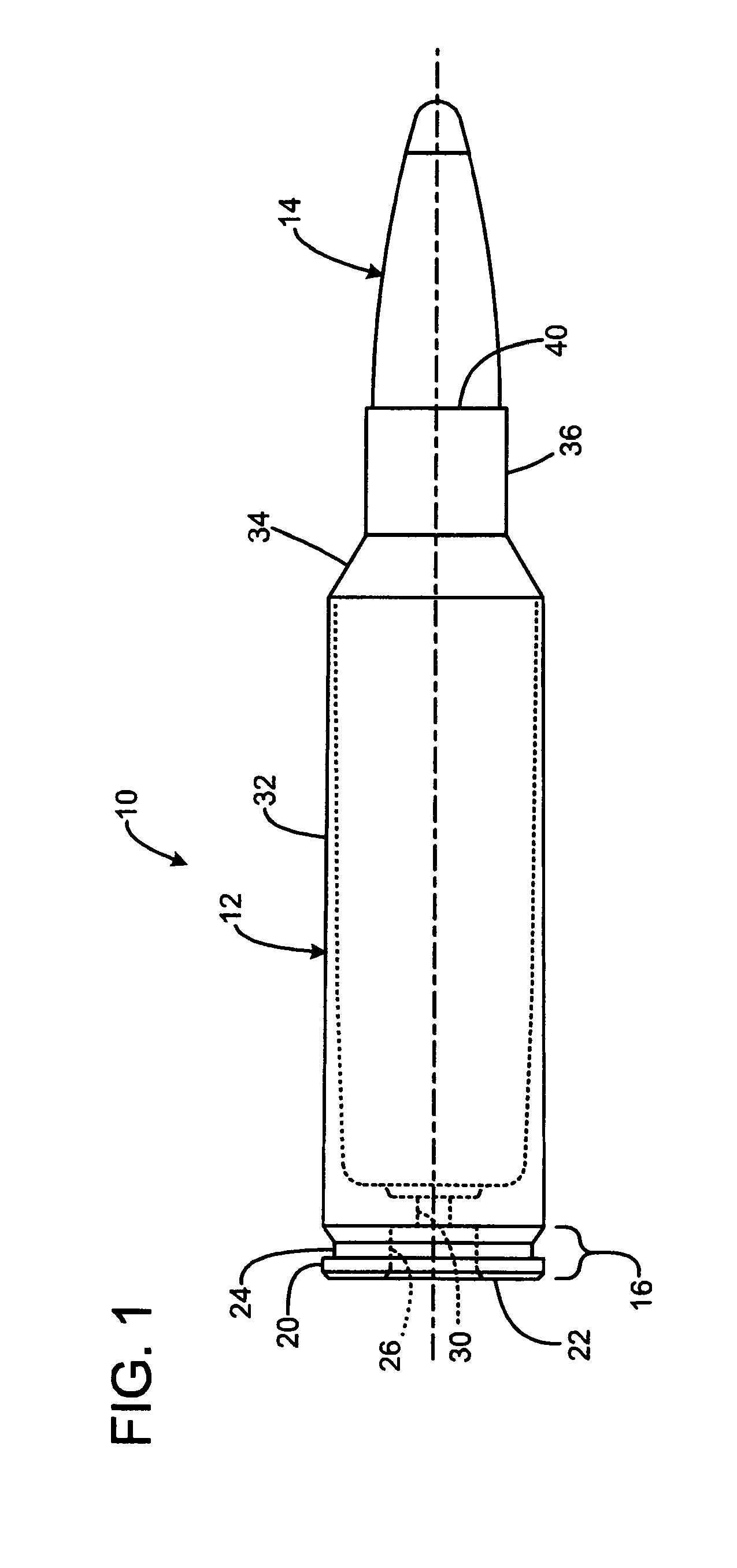
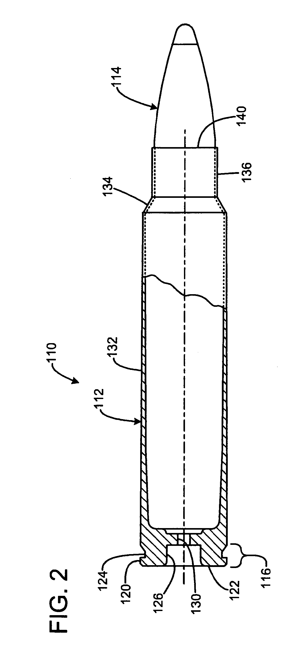
[0027]FIG. 1 shows a rifle cartridge 10 designated “300 Ruger” having a brass case 12 containing a charge of powder (not shown), with a bullet 14 received in a forward end of the case.

[0028]The case has a head 16 including a rim 20 nearest the rear head face 22 of the head, and an extraction groove 24 forward of the rim. A primer pocket 26 is centrally defined in the face 22, and communicates via a flash hole 30 with the interior of the case in which the powder charge is contained. The case has a main body portion 32 that is a gently tapered, nearly cylindrical conical portion extending forward from the groove 24. A more steeply tapered shoulder 34 transitions from the forward end of the body to a smaller essentially cylindrical neck 36, which has a forward end defining the mouth 40 that receives the bullet 14.

[0029]In the illustrated embodiment, the case head rim has a diameter of 0.532 (all dimensions in inches)+0.000 / −0.010.

[0030]The groove has a diameter of 0.475+0.000 / −0.020.

[0...


PUM


Abstract

The present invention overcomes the limitations of the prior art by providing a centerfire rifle cartridge with a case having a head having a rim, a body extending from the head to a tapered shoulder, and a neck extending from the shoulder and defining a mouth receiving a bullet. The body has a straight external surface free of a protruding belt, and has a maximum diameter sized to closely fit for operation within a standard action of magnum width. The cartridge has an overall length sized to closely fit for operation within a standard action such as a short action or a long action.

Description

FIELD OF THE INVENTION[0001]This invention relates to the firearm ammunition, and more particularly to centerfire cartridges for rifles.BACKGROUND AND SUMMARY OF THE INVENTION[0002]Rifle cartridges for firearms are available in a wide range of shapes and sizes for different applications. However, the variations are not infinite, and there are important constraints on cartridge dimensions. A typical rifle cartridge has a bottleneck shape with a slightly tapered nearly cylindrical body extending from a base or head to a much more tapered conical shoulder that transitions to a nearly cylindrical neck that receives a bullet. The case head typically has a groove near the head to provide a rim for a rifle extractor to engage, enabling removal of the case from a rifle chamber after firing.[0003]Some cartridges are “belted”, in that they have a larger diameter band near the head, with a forward facing step. The main body portion has a slightly smaller diameter than the belted portion. When ...

Claims


Application Information

Patent Timeline
Patent Type & Authority Patents(United States)
IPC IPC(8): F42B5/02
CPCF42B5/025
Inventor MITTELSTAEDT, MITCHELL T.
Owner HORNADY MFG CO
Learn More