Battery module, electric storage device and electric system
a battery module and electric storage technology, applied in the direction of cell components, electrical equipment, cell temperature control, etc., can solve the problem of not being able to meet the requirements of a battery module of limited size, and achieve the effect of not being able to meet the requirements of a limited size electric storage devi
- Summary
- Abstract
- Description
- Claims
- Application Information
AI Technical Summary
Benefits of technology
Problems solved by technology
Method used
Image
Examples
first embodiment
[0053]A first embodiment of the present invention will now be explained with reference to FIGS. 1 through 8. Firstly, the configuration of an in-vehicle electric system (an electric machine drive system) will be explained with reference to FIG. 6.
[0054]In an operating mode where rotative power is necessary, such as during the power running of the vehicle or at the internal-combustion engine starting, the in-vehicle electric system of the present embodiment drives a motor generator 200, which is a three-phase AC (alternate-current) synchronous motor, as a motor, and supplies driven bodies such as wheels and the engine with the generated rotative power. For this purpose, the in-vehicle electric system of the present embodiment outputs DC (direct-current) power from an electric storage device 100, which is an in-vehicle power source, converts the DC power to three-phase AC power by an inverter device 300, which is an electric power conversion device, and supplies the motor generator 20...
second embodiment
[0188]The second embodiment of the present invention will now be explained with reference to FIG. 9. While in the first embodiment the lithium-ion cells 11 are cylindrical (columnar), in the present embodiment the lithium-ion cells 11 are rectangular (square prism). The length of a side at a cross-section perpendicular to the transverse direction of the lithium-ion cell 11 is the same as the diameter D of the cylindrical lithium-ion cell of the first embodiment.
[0189]The rest of the configuration is identical to that of the first embodiment. Therefore, a component in common with the first embodiment is attached with a reference symbol identical to that of the first embodiment in FIG. 9 and the explanation thereon is omitted.
[0190]According to the present embodiment described above, the operational effects same as those of the first embodiment can be achieved.
third embodiment
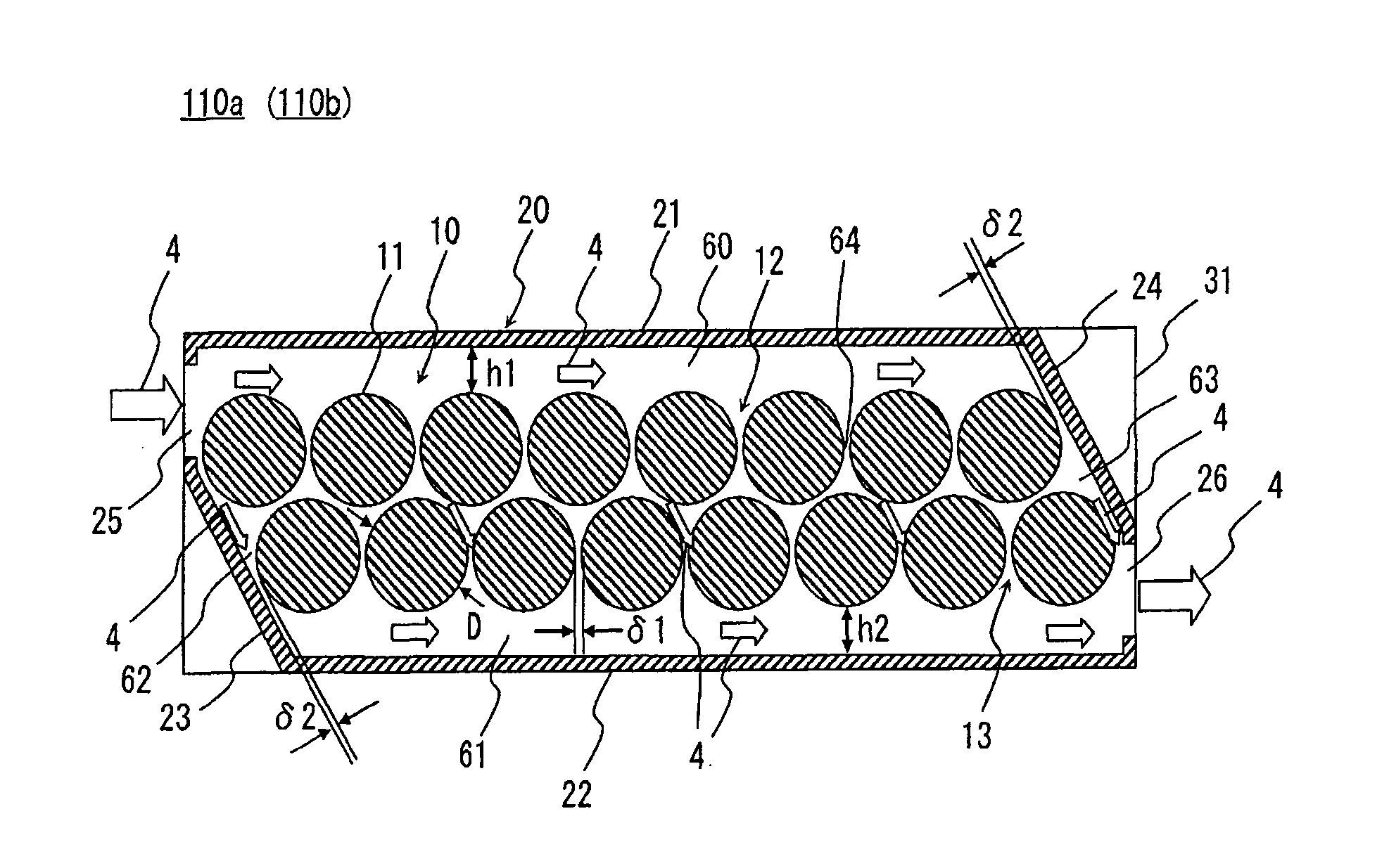
[0191]The third embodiment of the present invention will now be explained with reference to FIG. 10. The present embodiment is a modification of the first embodiment, wherein the height of the inlet-side passage 60. As shown in FIG. 10, the height h1 between the closest regions to the inlet passage forming plate 21 of the lithium-ion cells 11 constituting the first cell string 12 and the inner wall of the inlet passage forming plate 21 in the height direction is configured to be larger than the height of the outlet-side passage 61, i.e., the height h2 between the closest regions to the outlet passage forming plate 22 of the lithium-ion cells 11 constituting the second cell string 13 and the inner wall of the outlet passage forming plate 22 in the height direction. Thus, the size ratio of the height h2 of the outlet-side passage 61 to the diameter D of the lithium-ion cell 11 is configured to be larger than 0.25˜0.5 which is the size ratio of the height h1 of the inlet-side passage 6...
PUM
| Property | Measurement | Unit |
|---|---|---|
| output voltage | aaaaa | aaaaa |
| voltage | aaaaa | aaaaa |
| voltage | aaaaa | aaaaa |
Abstract
Description
Claims
Application Information
 - R&D
- Intellectual Property
- Life Sciences
- Materials
- Tech Scout
- Unparalleled Data Quality
- Higher Quality Content
- 60% Fewer Hallucinations
Browse by: Latest US Patents, China's latest patents, Technical Efficacy Thesaurus, Application Domain, Technology Topic, Popular Technical Reports.
© 2025 PatSnap. All rights reserved.Legal|Privacy policy|Modern Slavery Act Transparency Statement|Sitemap|About US| Contact US: help@patsnap.com


