Method for measuring airspeed by optical air data sensor
a technology of optical air data and airspeed, which is applied in the field of air data sensors, can solve the problems of high measurement error at low velocity, inability to measure velocity in low-speed range, and inability to achieve velocity measurements inherently impossible,
- Summary
- Abstract
- Description
- Claims
- Application Information
AI Technical Summary
Benefits of technology
Problems solved by technology
Method used
Image
Examples
example 1
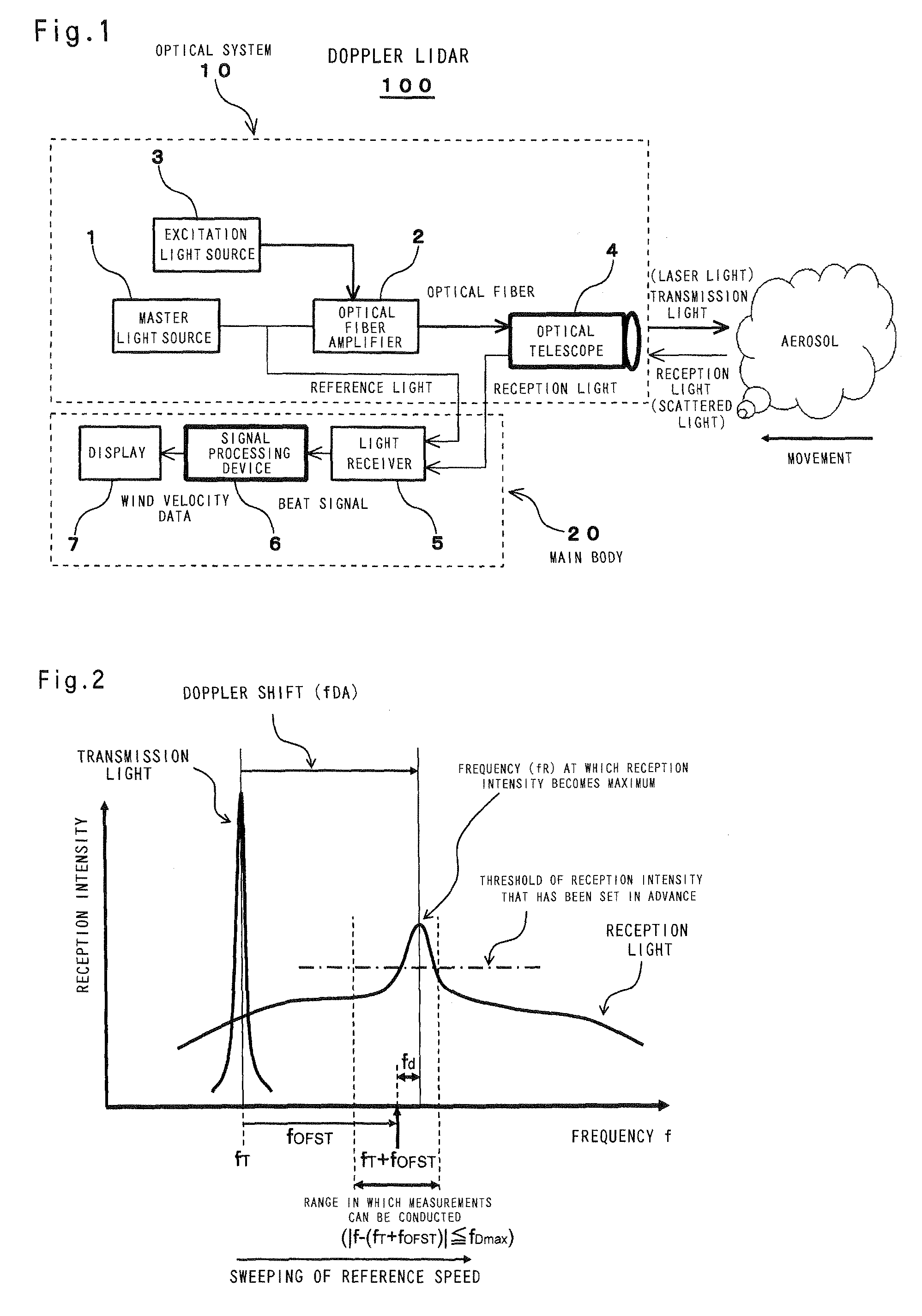
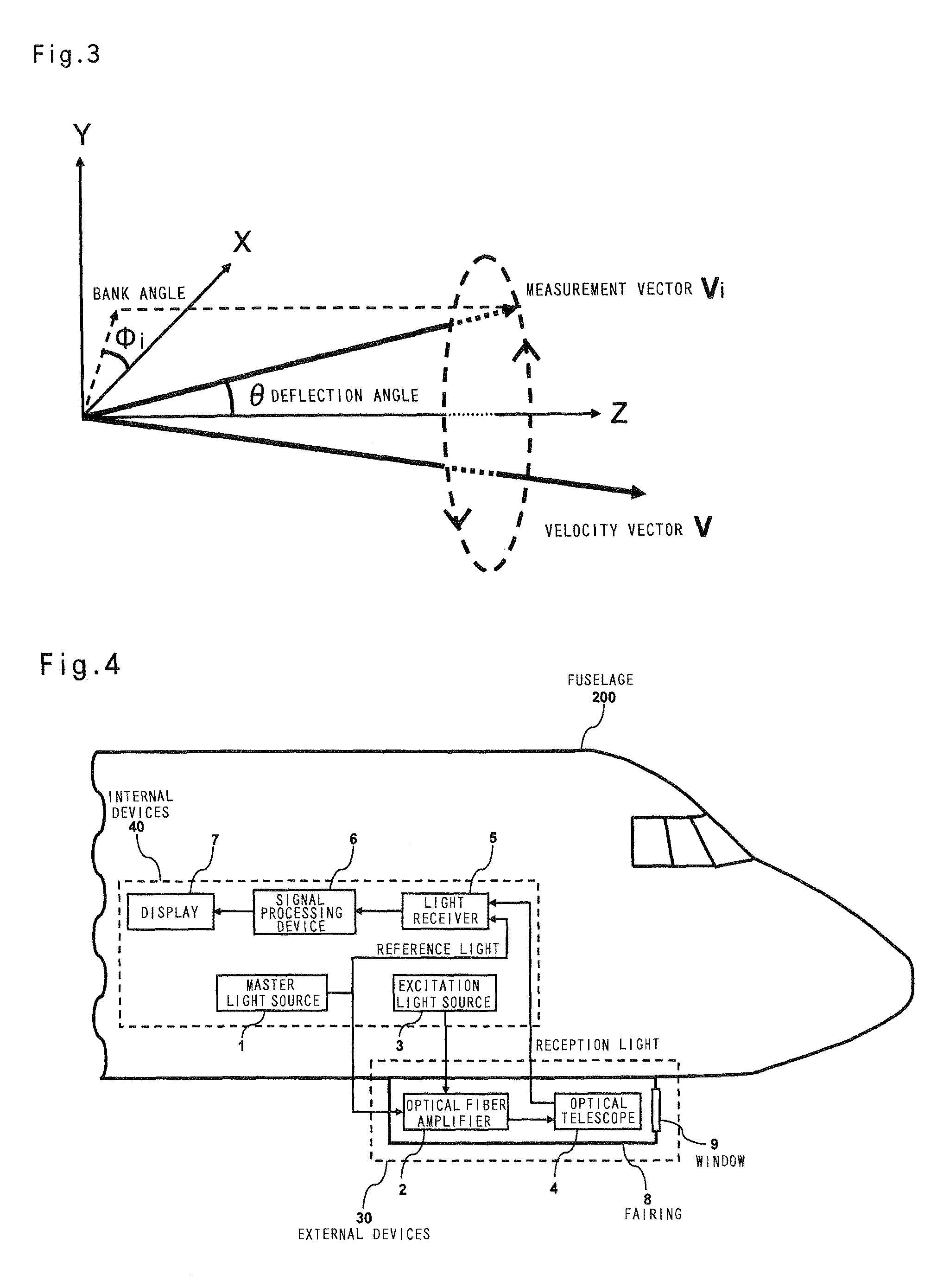
[0078]FIG. 4 is an explanatory drawing illustrating the configuration of a true airborne airspeed measurement device in accordance with the present invention. As shown in the figure, an optical telescope and an optical fiber amplifier are mounted on a lower surface of a fuselage, and the externally installed devices are covered with a fairing 8 to reduce air resistance. A window 9 is disposed in the direction in which a laser light is transmitted, thereby enabling the transmission of a laser light and the reception of a scattered light. In the present example, a configuration is used in which an optical telescope and an optical fiber amplifier are mounted on a lower surface of a fuselage, but this configuration is not limiting, and mounting these devices on the side surface of the fuselage nose and lower surface of a main wing can be also considered. Thus, the devices may be mounted in a location where the individual fuselage configuration enables easy installation. The devices othe...
example 2
[0081]Once the airspeed is determined, as in Example 1, the measurement value of the immediately preceding cycle is used as a frequency offset value. However, depending on various conditions such as atmospheric conditions, the measurement value can also include noise. Therefore, the measurement value of the immediately preceding cycle is an average value of a plurality of values, rather than one measurement value. In airspeed measurements performed with a typical Pitot tube, abrupt changes can decrease visibility for the pilot. Therefore, an orifice is introduced in a conduit system to improve the display contrast. For this reason, with respect to the airspeed measured by a Doppler LIDAR, the configuration is also appropriate for displaying a moving average value of about 3 s.
[0082]When measurements temporarily become impossible and the reception intensity within the frequency measurement range does not reach the threshold that has been set in advance, for example, because of a larg...
example 3
[0083]FIG. 5 is an explanatory drawing illustrating a method for measuring velocity components, namely, a transverse component Vx of airspeed (in the X axis direction in FIG. 5), a vertical component Vy of airspeed (in the Y axis direction in FIG. 5), and a longitudinal component Vz of airspeed (in the Z axis direction in FIG. 5), by fixing the deflection angle θ and rotating the bank angle φi, as a laser beam scanning method. For example, the scanned laser beam is stopped in three points that are not in the same plane, velocity components V1, V2, V3 of the measurement vector are measured, and velocity components in the X axis direction, Y axis direction, and Z axis direction are calculated from the measured velocity components in the three points (three-point measurement). In this case, the velocity vector V=(Vx, Vy, Vz) can be determined in the following manner.
[0084][VxVyVz]=[cosϕ1cos(π2-θ)sinϕ1cos(π2-θ)sin(π2-θ)cosϕ2cos(π2-θ)sinϕ2cos(π2-θ)sin(π2-θ)cosϕ3cos...
PUM
 Abstract
Description
Claims
Application Information
 - R&D
- Intellectual Property
- Life Sciences
- Materials
- Tech Scout
- Unparalleled Data Quality
- Higher Quality Content
- 60% Fewer Hallucinations
Browse by: Latest US Patents, China's latest patents, Technical Efficacy Thesaurus, Application Domain, Technology Topic, Popular Technical Reports.
© 2025 PatSnap. All rights reserved.Legal|Privacy policy|Modern Slavery Act Transparency Statement|Sitemap|About US| Contact US: help@patsnap.com


