
Power transmission mechanism for parallel hybrid vehicle

a technology of power transmission mechanism and hybrid vehicle, which is applied in the direction of engine-driven generators, transportation and packaging, and transportation, etc., can solve the problems of insufficient strength and insufficient durability of dog clutches, high precision and complicated synchronization control of rotation speed, and achieve the effects of reducing engine load, improving mileage, and reducing electric loss

Inactive Publication Date: 2013-04-30
NISSAN DIESEL MOTOR CO
View PDF17 Cites 11 Cited by
  • Summary
  • Abstract
  • Description
  • Claims
  • Application Information

AI Technical Summary

Benefits of technology

The patent text discusses a system where a motor is used to generate power. When the motor is not in operation, the output shaft of the motor is fixed, which reduces mechanical and electric loss and lowers the load on the engine, resulting in improved mileage. The system also uses a planetary gear mechanism that allows for smooth connection and disconnection of the engine and motor, and is strong enough for heavy-duty trucks requiring high power.

Problems solved by technology

However, smooth connection / disconnection of the dog clutch forming the aforesaid clutch mechanism 21 requires highly precise and complicated synchronization control of the rotation speeds.
Further, the power transmission mechanism of the hybrid system in FIG. 7 is structured on assumption that it is mounted on a small two to three ton truck, and if it is to be applied to a heavy-duty truck requiring a high motor power, there is a concern about insufficient strength and insufficient durability of the dog clutch.

Method used


Image

  • Power transmission mechanism for parallel hybrid vehicle
  • Power transmission mechanism for parallel hybrid vehicle
  • Power transmission mechanism for parallel hybrid vehicle

Examples


Embodiment Construction

[0024]Hereinafter, embodiments of the present invention will be described in detail based on the drawings.

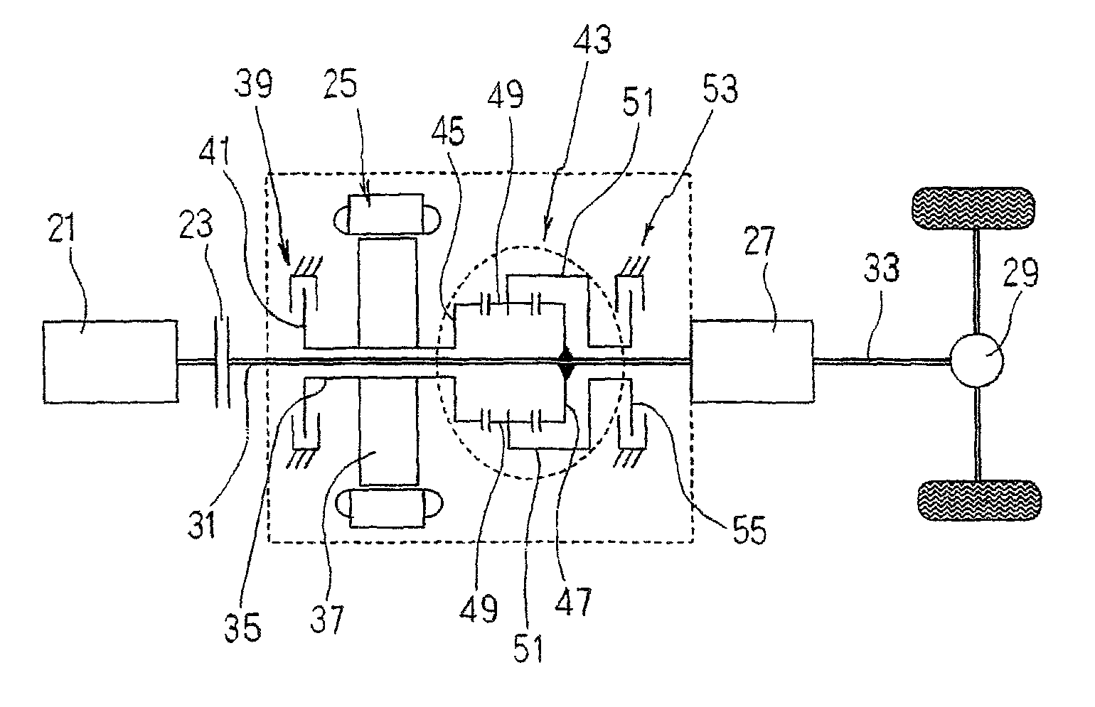
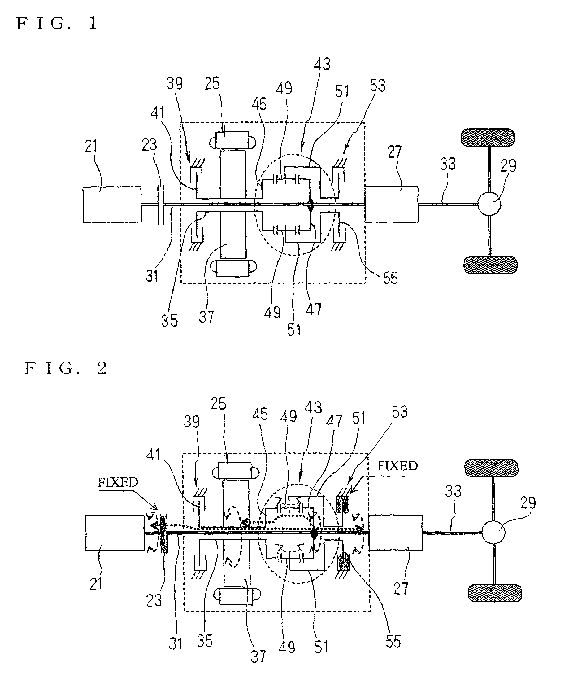
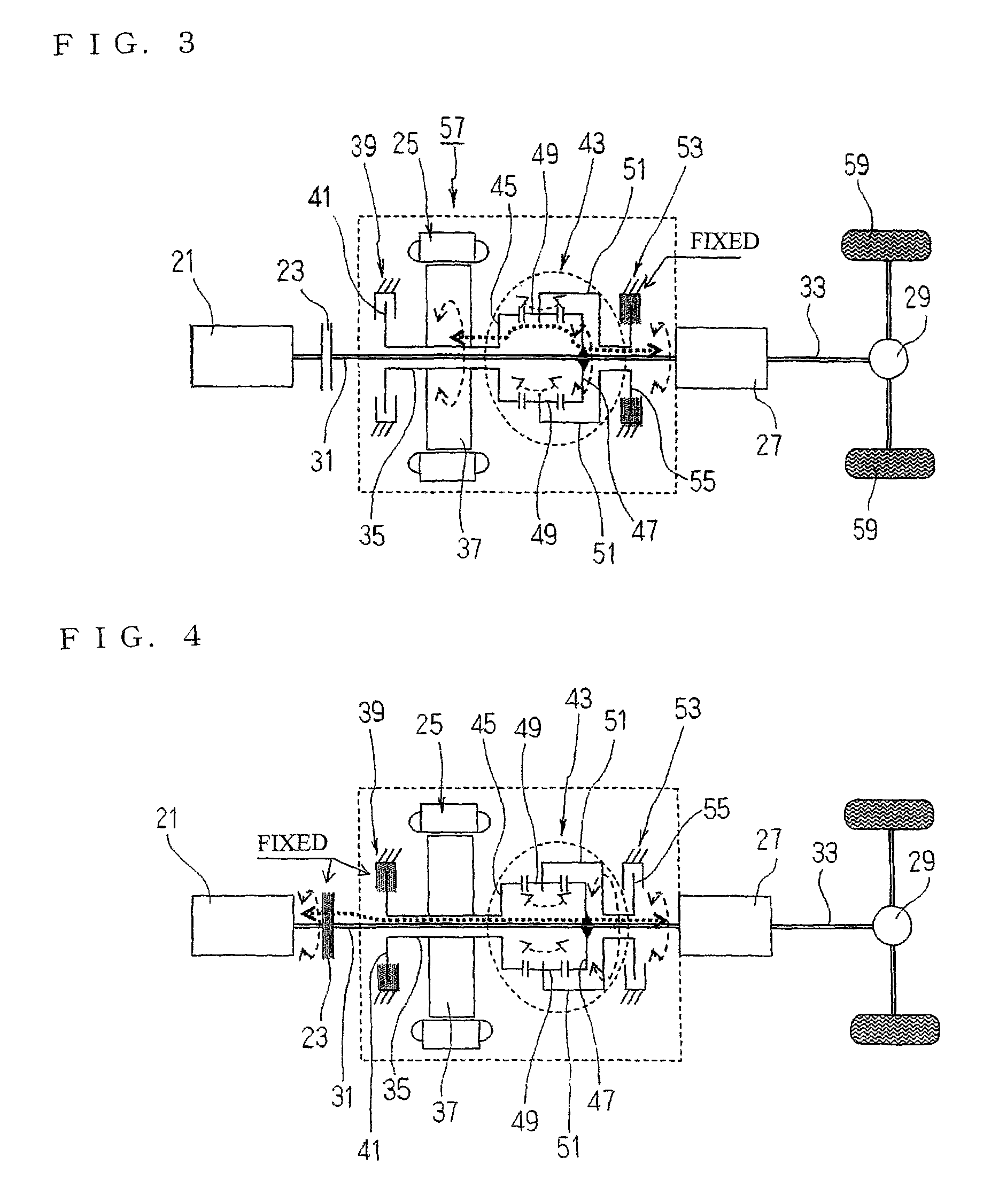
[0025]FIG. 1 to FIG. 4 illustrate a first embodiment of a power transmission mechanism of a parallel hybrid vehicle according to claim 1, and as in the conventional example in FIG. 6, the arrangement of a driving system of a hybrid system according to this embodiment is such that an engine 21, a main clutch (single plate clutch) 23, a motor (motor / generator) 25, a transmission 27, and a final reduction gear 29 are all arranged coaxially in the order mentioned. An engine drive shaft system 31 extends from the main clutch 23 to the transmission 27, and a propeller shaft 33 is coupled between the transmission 27 and the final reduction gear 29.

[0026]Further, in the drawings, 35 denotes a motor output shaft attached to a rotor 37 of the motor 25, and the motor output shaft 35 is structured separately from the engine drive shaft system 31 and is rotatably supported by a not-illustrat...


PUM


Abstract

A proposition is to provide a power transmission mechanism for parallel hybrid vehicle that is capable of smoothly combining / separating input / output powers of a motor and an engine, and is applicable to a large hybrid vehicle by ensuring sufficient strength of a mechanism for combining and separating the input / output powers.It is characterized by including a motor output shaft of the motor / generator rotatable separately from an engine drive shaft system extending from a main clutch to a transmission, a motor-brake mounted on one end side of the motor output shaft to release / fix the motor output shaft, and a planetary gear mechanism mounted between another end side of the motor output shaft and the engine drive shaft system and including a sun gear provided on the other end side of the motor output shaft, an outer gear provided on the engine drive shaft system and having a gear ratio to the sun gear of 1:1, a plurality of planetary gears with which the sun gear and the outer gear are engaged, and a planetary carrier picking up orbital motions of the planetary gears, and a gear brake mounted on one end side of the planetary carrier to release / fix the planetary carrier.

Description

CROSS-REFERENCE TO RELATED APPLICATION[0001]This application is a U.S. National Stage application under 35 U.S.C. §371 claiming benefit of prior filed International Application Number PCT / JP2009 / 006187, filed Nov. 18, 2009, in which the International Application claims a priority date of May 7, 2009 based on prior filed Japanese Patent Application Number 2009-112749, the entire contents of which are incorporated herein by reference.TECHNICAL FIELD[0002]The present application relates to a power transmission mechanism for hybrid vehicle, more particularly, to a power transmission mechanism for parallel hybrid vehicle using powers of an engine and a motor / generator in combination.BACKGROUND ART[0003]As disclosed in Non-patent Document 1, with the aim of improving mileage by reducing a load applied to an engine in a commercial vehicle such as a truck, there has recently been proposed a parallel hybrid system using an assisting power of a motor during driving where a load is applied to ...

Claims


Application Information

Patent Timeline
Patent Type & Authority Patents(United States)
IPC IPC(8): F16H3/72B60L50/16
CPCB60K6/365B60K6/387B60K6/48B60K6/547B60L7/18B60L7/26B60L11/14Y02T10/70B60L2270/145Y02T10/6221Y02T10/7077B60K2006/381B60L2200/26B60L50/16Y02T10/62Y02T10/7072
Inventor YAMADA, YOSHIAKIHIKIRI, KUNIHIKONAKAMURA, SHUICHIITANI, KOUICHI
Owner NISSAN DIESEL MOTOR CO
Learn More