Region-growing algorithm

a technology of region growth and algorithm, applied in image enhancement, diagnostic recording/measuring, instruments, etc., can solve problems such as leakage and unexpected increase, and achieve the effects of reducing false branches, reducing the appearance of “holes” in the central segmented area of the model, and increasing growth

Active Publication Date: 2013-04-23
TYCO HEALTHCARE GRP LP
View PDF154 Cites 17 Cited by
  • Summary
  • Abstract
  • Description
  • Claims
  • Application Information

AI Technical Summary

Benefits of technology

[0015]Another advantage of the present invention is that the appearance of “holes” in the central segmented area of the model is greatly reduced.
[0016]Yet another advantage of the present invention is a reduced number of false branches. Because each iteration is analyzed, growth is controlled and false branches are prevented from growing.
[0017]Another advantage of the present invention is that the branches grown have an increased length, due to an optimized threshold as well as secondary growing efforts.
[0018]Still another advantage of the present invention is reduced importance on initial threshold value selection. Through experimentation, it has been found that this algorithm is self-correcting, yielding virtually identical results regardless of the initial threshold used, so long as the thresholds are relatively high.

Problems solved by technology

If the voxels are not growing according to an expected rate, the unexpected increase is identified as leakage.

Method used


Image

  • Region-growing algorithm
  • Region-growing algorithm

Examples


Embodiment Construction

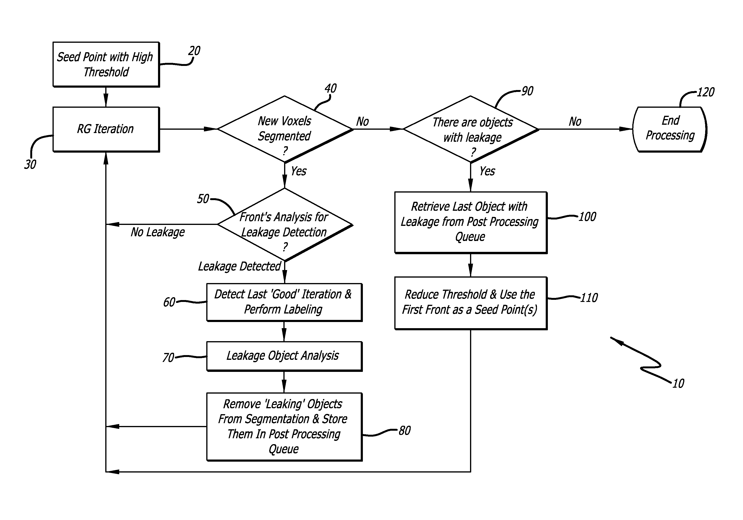
[0020]The technique 10 of the present invention is charted in the flowchart presented as FIG. 1. The technique 10 begins at 20 by selecting a starting point for the segmentation of the CT data. For example, selecting a point in the trachea is a logical starting point as it is the largest, and most proximal airway, and easily recognizable on a CT scan. Preferably, the starting point is a single voxel inside the trachea that is centered and meets a high threshold value. In other words, a voxel which is clearly air is selected. Any point from which further adjacent voxels are analyzed is hereinafter referred to as a “seed point”. The starting point is the first seed point.

[0021]At 30 the propagation process is initiated by designating adjacent voxels around the starting point. This designation is known as segmentation, and it indicates that the new voxels met the threshold level for air. Because the starting point is preferably selected in the trachea, and it is not desired to grow the...


PUM


Abstract

A technique for automatically generating a virtual model of a branched structure using as an input a plurality of images taken of the branched structure. The technique employs an algorithm that avoids inaccuracies associated with sub-optimal threshold settings by “patching” holes or leaks created due to the inherent inconsistencies with imaging technology. By “patching” the holes, the algorithm may continue to run using a more sensitive threshold value than was previously possible.

Description

RELATED APPLICATIONS[0001]This application claims priority to U.S. Provisional Application Ser. No. 61 / 300,423 filed Feb. 1, 2010 entitled Region-Growing Algorithm, which is hereby incorporated herein by reference in its entirety.BACKGROUND OF THE INVENTION[0002]Navigating the airways of the lungs has always presented challenges to physicians attempting to diagnose and treat lesions trans-luminally. As such, numerous navigational aids and imaging tools have been developed and / or utilized to provide physicians a “map” of the lungs.[0003]One such tool is a CT scanner. CT scanners use X-ray technology to take multiple scans or “slices” of the lungs. These scans each represent a cross-section of the lungs and can be viewed individually or assembled, via computer programs, to form a three-dimensional CT model. However, CT scans, like most images using X-ray technology, are somewhat cloudy and translucent in nature and difficult to view. As such, computer graphics techniques are employed ...

Claims


Application Information

Patent Timeline
Patent Type & Authority Patents(United States)
IPC IPC(8): G06K9/00A61B5/08
CPCG06K9/342G06T7/0081G06T7/0012G06T2207/10081G06T2207/20156G06T2207/30061G06T2207/20141G06T7/11G06T7/187G06V10/267G06T7/136
Inventor AVERBUCH, DORIANKREININ, YURI
Owner TYCO HEALTHCARE GRP LP
Why Eureka
Try Eureka