
Power factor correction converter including operation mode determination unit

a power factor and converter technology, applied in the field of acdc converters, can solve the problems of harmonic current generation, distortion of input current, discontinuous input current, etc., and achieve the effects of small amount of arithmetic processing, small burden on the processor, such as the dsp, and improved harmonic suppression and power factor

Inactive Publication Date: 2013-04-23
MURATA MFG CO LTD
View PDF34 Cites 19 Cited by
  • Summary
  • Abstract
  • Description
  • Claims
  • Application Information

AI Technical Summary

Benefits of technology

The present invention relates to a method for controlling the operation mode of an electricity distribution system, which can improve harmonic suppression and power factor regardless of the load. The method uses a current waveform that matches the voltage waveform, which can be determined by performing current value sampling up to two times per switching period. This reduces the amount of arithmetic processing required and allows for the use of lower-speed processors.

Problems solved by technology

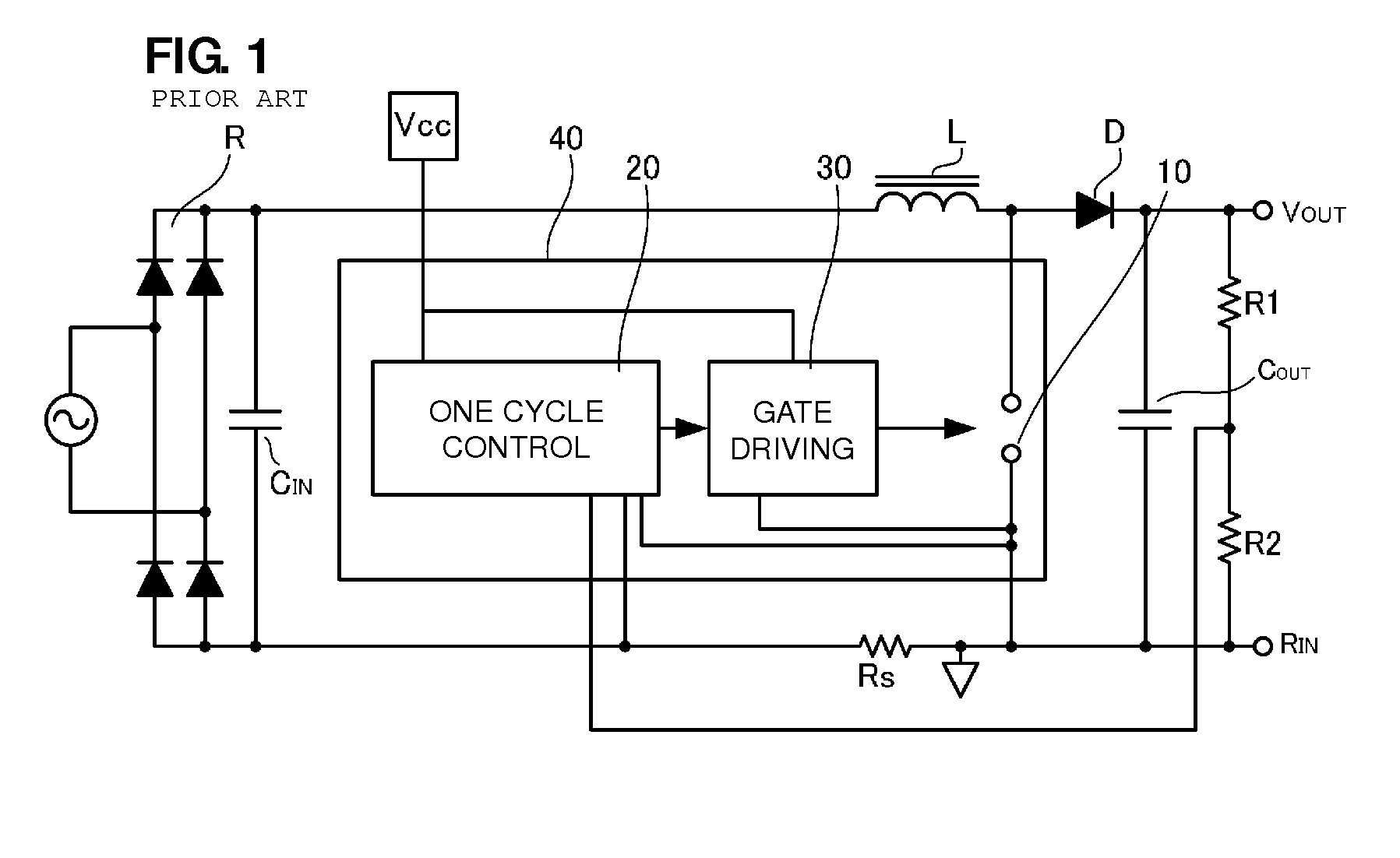
General switching power supply devices, which receive a commercial alternating-current power supply as an input power supply, rectify and smooth the commercial alternating-current power supply and thereby convert the commercial alternating-current power supply into a direct-current voltage, and since the direct-current voltage is then switched using a DC-DC converter, the input current becomes discontinuous and significantly distorted from a sine wave.
This causes generation of harmonic currents.
However, since it is assumed that the PFC converter of Japanese Unexamined Patent Application Publication No. 2006-513682 will operate in a continuous current mode, if the PFC converter operates in a discontinuous current mode when the load is light, distortions are generated in the input current.
However, in reality, if a state arises in which the load increases and the PFC converter operates in a continuous current mode, distortions are generated in the input current.

Method used


Image

  • Power factor correction converter including operation mode determination unit
  • Power factor correction converter including operation mode determination unit
  • Power factor correction converter including operation mode determination unit

Examples


first preferred embodiment

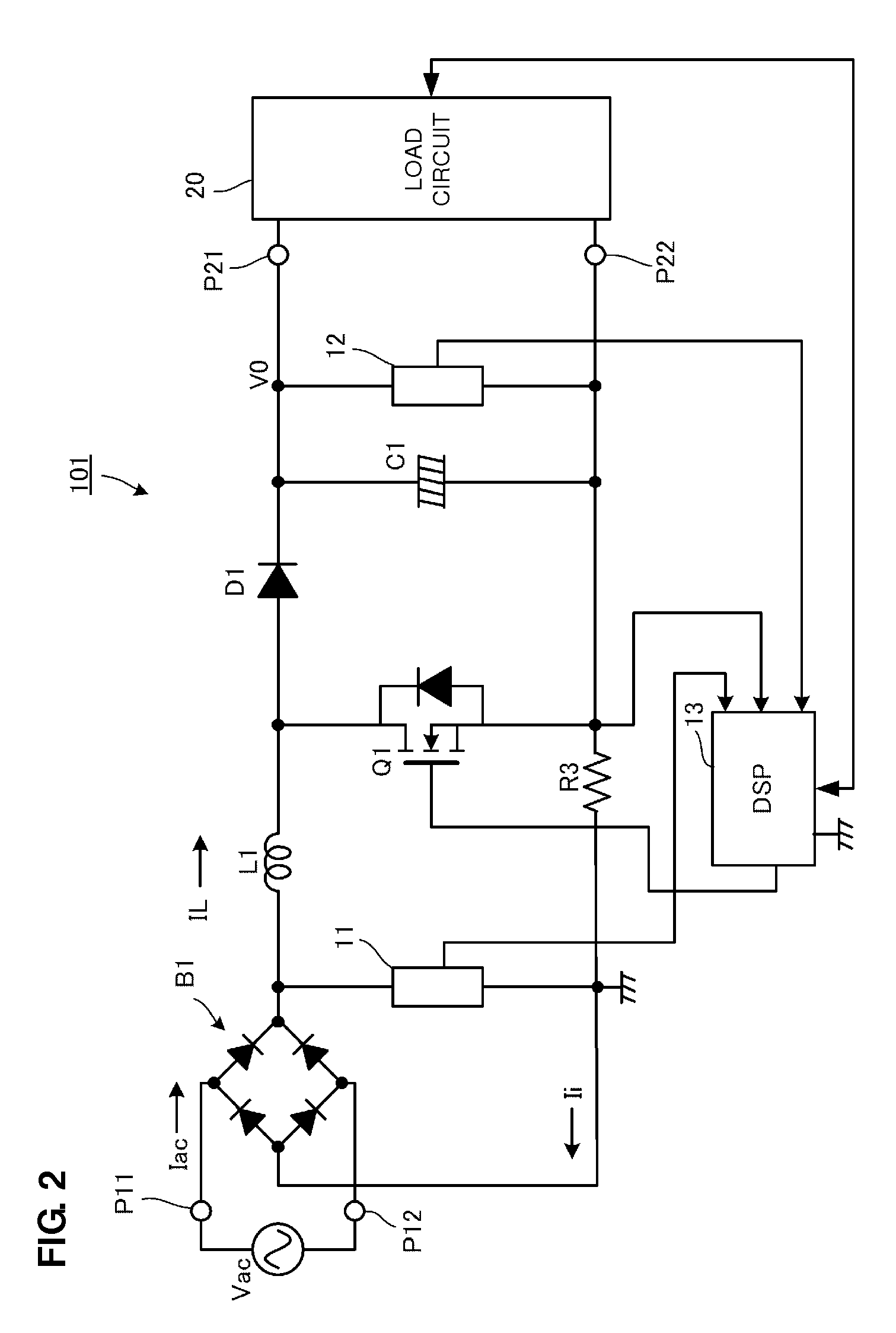
[0039]A PFC converter according to a first preferred embodiment of the present invention will be described with reference to FIGS. 2 to 5B.

[0040]FIG. 2 is a circuit diagram of a PFC converter 101 according to a first preferred embodiment of the present invention. In FIG. 2, symbols P11 and P12 denote input ports of the PFC converter 101 and symbols P21 and P22 denote output ports of the PFC converter 101. An alternating-current input power supply Vac, which is a commercial alternating-current power supply, is input to the input ports P11 and P12 and a load circuit 20 is connected to the output ports P21 and P22.

[0041]The load circuit 20 is, for example, a circuit of an electronic appliance that receives a power supply through, for example, a DC-DC converter or a DC-DC converter thereof.

[0042]A diode bridge B1, which is a rectifier circuit that full-wave rectifies an alternating-current voltage of the alternating-current input power supply Vac, is provided in an input stage of the PF...

second preferred embodiment

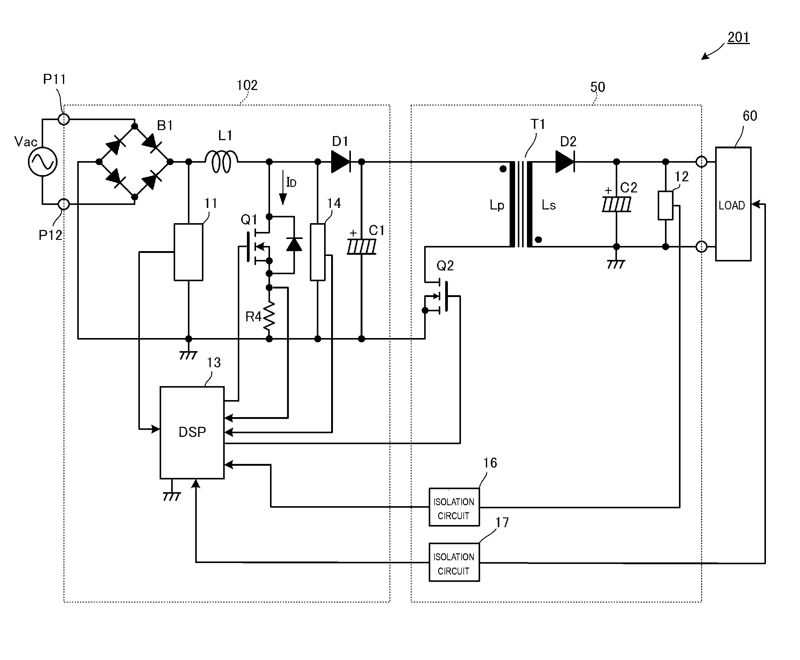
[0062]FIG. 6 is a circuit diagram of a switching power supply device 201 according to a second preferred embodiment of the present invention.

[0063]The switching power supply device 201 in FIG. 6 preferably includes a PFC converter 102 and a DC-DC converter 50. A load 60 is connected to the output of the DC-DC converter 50.

[0064]An alternating-current input power supply Vac, which is a commercial alternating-current power supply, is input to input ports P11 and P12 of the PFC converter 102 and the DC-DC converter 50 is connected to an output section of the PFC converter 102. The PFC converter 102 preferably includes a diode bridge B1 that full-wave rectifies the alternating-current input power supply Vac, an inductor L1 that is connected to the output of the diode bridge B1, a switching element Q1, a diode D1, a smoothing capacitor C1, a current detection resistor R4 that is connected in series with the switching element Q1, an input voltage detection circuit 11 and a switching eleme...

third preferred embodiment

[0077]FIG. 8 is a circuit diagram of a switching power supply device 202 according to a third preferred embodiment of the present invention.

[0078]The switching power supply device 202 in FIG. 8 preferably includes a PFC converter 103 and a DC-DC converter 50. A load 60 is connected to the output of the DC-DC converter 50.

[0079]An alternating-current input power supply Vac, which is a commercial alternating-current power supply, is input to input ports P11 and P12 of the PFC converter 103 and the DC-DC converter 50 is connected to an output section of the PFC converter 103. The PFC converter 103 preferably includes a diode bridge B1 that full-wave rectifies the alternating-current input power supply Vac, an inductor L1 that is connected to the output of the diode bridge B1, a switching element Q1, a diode D1, a smoothing capacitor C1, a current detection resistor R4 that is connected in series with the switching element Q1 and an input voltage detection circuit 11. A boost-type chopp...


PUM


Abstract

A power factor correction converter includes a diode bridge that rectifies an alternating-current voltage input from an alternating-current input power supply Vac, a series circuit including an inductor and a switching element, a rectifying smoothing circuit connected in parallel with the switching element and including a diode and a smoothing capacitor, and a digital signal processing circuit that controls turning on and off of the switching element such that the input current input from the alternating-current input power supply Vac comes to have a similar shape to the alternating-current voltage. The current flowing through the inductor in the off period of the switching element is detected by using a current detection resistor, the operation mode is determined on the basis of the inductor current IL at a predetermined timing and the switching element is optimally controlled in accordance with the operation mode.

Description

BACKGROUND OF THE INVENTION[0001]1. Field of the Invention[0002]The present invention relates to an AC-DC converter that receives an input of an alternating-current power supply voltage and that outputs a direct-current voltage, and in particular relates to a PFC (power factor correction) converter that improves the power factor.[0003]2. Description of the Related Art[0004]General switching power supply devices, which receive a commercial alternating-current power supply as an input power supply, rectify and smooth the commercial alternating-current power supply and thereby convert the commercial alternating-current power supply into a direct-current voltage, and since the direct-current voltage is then switched using a DC-DC converter, the input current becomes discontinuous and significantly distorted from a sine wave. This causes generation of harmonic currents.[0005]In Japan, Europe, and elsewhere, there are regulations concerning harmonic currents, classified in accordance with...

Claims


Application Information

Patent Timeline
Patent Type & Authority Patents(United States)
IPC IPC(8): H02M7/155H02M7/217H02M7/17
CPCH02M1/4225Y02B70/126H02M2001/0012Y02B70/10H02M1/0012H02M1/0085
Inventor UNO, YOSHIYUKI
Owner MURATA MFG CO LTD
Learn More