
PTC device

a positive temperature coefficient and ptc technology, applied in the direction of positive temperature coefficient thermistors, resistors, emergency protective circuit arrangements, etc., can solve the problems of increased resistance in ptc components, insufficient cases, and metal filler oxidation, so as to improve the yield the design constraints of ptc devices or ptc components are eased, and the dimensional precision of ptc devices is improved

Inactive Publication Date: 2013-04-16
LITTELFUSE JAPAN GK
View PDF14 Cites 6 Cited by
  • Summary
  • Abstract
  • Description
  • Claims
  • Application Information

AI Technical Summary

Benefits of technology

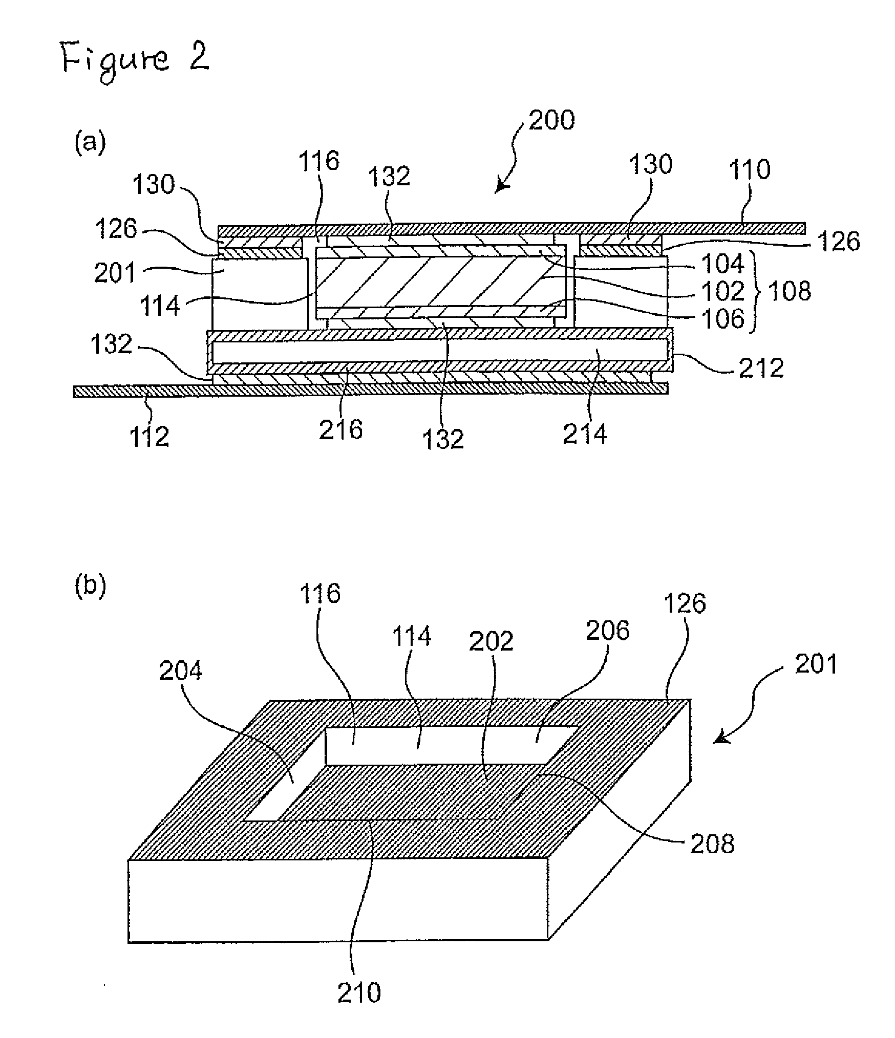
[0009]As a result of the inventor's study as to the above problem, it has been found that by encapsulating a PTC component in a ceramic package generally used in a semiconductor device and the like, the oxidation of the metal filler contained in the PTC element can be effectively prevented even when the environment in which the PTC device is used contains a substance such as a solvent, as a result of which the resistance of the PTC component can be maintained low.
[0017]In the PTC device of the present invention, the ceramics constituting the ceramic package have solvent resistance, so that the oxidation of the metal filler which constitutes the PTC element by air or oxygen present in the ambient environment of the PTC device is effectively prevented when the PTC component is encapsulated within the ceramic package, even if the environment in which the PTC device is used contains a solvent, because the encapsulated state is substantially unaffected. Therefore, there is no need to provide a resin coating as described above around the PTC component. As a result, there is no need to take into account, when forming the resin coating, any outflow of a coating material for the formation of the resin coating on the PTC component onto an electrode surface of the PTC component for forming the resin coating on the PTC component (outflow of coating material onto a place of the component (such as a metal electrode surface) which requires electrical conduction may not allow the electrical conduction that the component requires to be secured). Therefore, design constraints for the PTC device or the PTC component are alleviated and the yield of the PTC device or the PTC component is improved.
[0018]Also, whereas the resin coating is not necessarily sufficient in its dimensional precision, the PTC device according to the present invention uses a ceramic package having a standard size, which substantially secure the device size, so that the dimensional precision of the PTC device is improved. As a result, the setting is facilitated when a user incorporates the PTC device in an electrical apparatus and the like. Further, since the ceramic material constituting the ceramic package is stable against an electrolyte in a battery (for example a secondary battery), the PTC device of the present invention may be incorporated inside the battery. As a result, the PTC device may be placed close to the heat source, improving the sensitivity of the PTC device to detect an abnormal condition and the reliability of the battery is improved.

Problems solved by technology

Such increase in resistance is not desirable in a PTC component that should essentially be low resistance.
Such a resin coating is basically effective in preventing the oxidation of the metal filler, but in some cases may not be sufficient depending on the environment in which the PTC device comprising the PTC component is used.
In this case, the metal filler may oxidize, as a result of which the PTC component may be likely not to function appropriately.
Therefore, it is a problem to be solved is to provide a PTC device wherein the PTC element will function appropriately even when the PTC device is used in an environment in which a substance such as a solvent is present which may affect the PTC device.

Method used


Image

  • PTC device
  • PTC device
  • PTC device

Examples


examples

[0070]The PTC device of the present invention shown in FIG. 4 was simulated using the following ceramic package, PTC component, and lead:

[0071]Ceramic package (manufactured by NGK Spark Plug Co., Ltd., made of aluminum oxide)

[0072]Size (outer dimensions): 4.8 mm×9.1 mm×1.3 mm (height)

[0073]Size of open-ended space: 3.4 mm×7.7 mm×1.05 mm (height)

[0074]Metal layer: Ni plating and then Au plating on Mo / Mn layer (corresponding to 404 and 406 in FIG. 4); Plated layer corresponds to 409 in FIG. 4.

[0075]PTC component (manufactured by Tyco Electronics Raychem, product name: PolySwitch)

[0076]Size: 2.3 mm×3.0 mm×0.43 mm (thickness)

[0077]Lead (made of nickel, size: 5 mm×20 mm×0.125 mm (thickness))

[0078]After disposing the PTC component within the open-ended space in the ceramic package, a lead was placed on the ceramic package, the opening defining said space was closed by welding the lead and the metal layer (406+409) on the periphery of the ceramic package to encapsulate the PTC component in...


PUM

PropertyMeasurementUnit
resistanceaaaaaaaaaa
Temperature Coefficientaaaaaaaaaa
conductiveaaaaaaaaaa

Abstract

There is provided a PTC device wherein its PTC element functions appropriately even when the PTC device is used in an environment in which solvent is present. The PTC device includes: (1) a polymer PTC component including a polymer PTC element and a first and a second metal electrodes disposed on both sides of the main surface thereof; (2) a lead connected to at least one of the metal electrodes of the polymer PTC component; and (3) a ceramic package having an open-ended space for accommodating the polymer PTC component, said open-ended space having at least one opening that defines the open-ended space. The lead closes said opening in order to isolate the polymer PTC component disposed in said open-ended space from the environment surrounding the ceramic package.

Description

FIELD OF THE INVENTION[0001]The present invention relates to a PTC (Positive Temperature Coefficient) device comprising a PTC component, in particular a PTC device comprising a PTC component that is used as a circuit protection device, as well as an electrical or electronic apparatus comprising such a device.BACKGROUND OF THE INVENTION[0002]Polymer PTC components are widely used in various electrical or electronic apparatuses to prevent important elements composing the apparatus from breaking down if an excessively large amount of current flows in the power circuit, etc. Such a component itself is well known, and commonly comprises a PTC element normally in laminar form and composed of a polymer composition of conductive fillers dispersed in a polymer, and metal electrodes, e.g. metal foil electrodes, disposed on the facing main surfaces thereof.[0003]For example, PTC devices having PTC components as described above and a lead or leads connected thereto are used in rechargeable batt...

Claims


Application Information

Patent Timeline
Patent Type & Authority Patents(United States)
IPC IPC(8): H01C7/10
CPCH01C7/028H01C7/021H01C7/02
Inventor KOYAMA, HIROYUKI
Owner LITTELFUSE JAPAN GK
Learn More