
Resist coating and developing apparatus, resist coating and developing method, resist-film processing apparatus, and resist-film processing method

a technology of resist coating and developing apparatus, applied in the direction of photomechanical apparatus, instruments, photosensitive materials, etc., can solve the problems of deteriorating properties as an integrated circuit, affecting the properties of a semiconductor device to be manufactured, and the inability to transfer the desired shape to a base layer, etc., to reduce the roughness of the resist pattern on the line width

Active Publication Date: 2013-04-16
TOKYO ELECTRON LTD
View PDF22 Cites 19 Cited by
  • Summary
  • Abstract
  • Description
  • Claims
  • Application Information

AI Technical Summary

Benefits of technology

The present invention provides a method and apparatus for coating and developing a resist material, as well as a method and apparatus for processing the resist-film. The aim is to reduce the roughness of the resist pattern's line width. The technical effect of the invention is to create a smoother resist pattern.

Problems solved by technology

In a case where a channel of such a width of a field-effect transistor (FET) is formed, if a line width roughness (LWR) of a resist pattern is large, voltage threshold values may become non-uniform, to thereby deteriorate properties as an integrated circuit and / or invite an abnormal operation.
In this case, a desired shape cannot be transferred to a base layer, which impairs properties of a semiconductor device to be manufactured.

Method used


Image

  • Resist coating and developing apparatus, resist coating and developing method, resist-film processing apparatus, and resist-film processing method
  • Resist coating and developing apparatus, resist coating and developing method, resist-film processing apparatus, and resist-film processing method
  • Resist coating and developing apparatus, resist coating and developing method, resist-film processing apparatus, and resist-film processing method

Examples


experiment 1

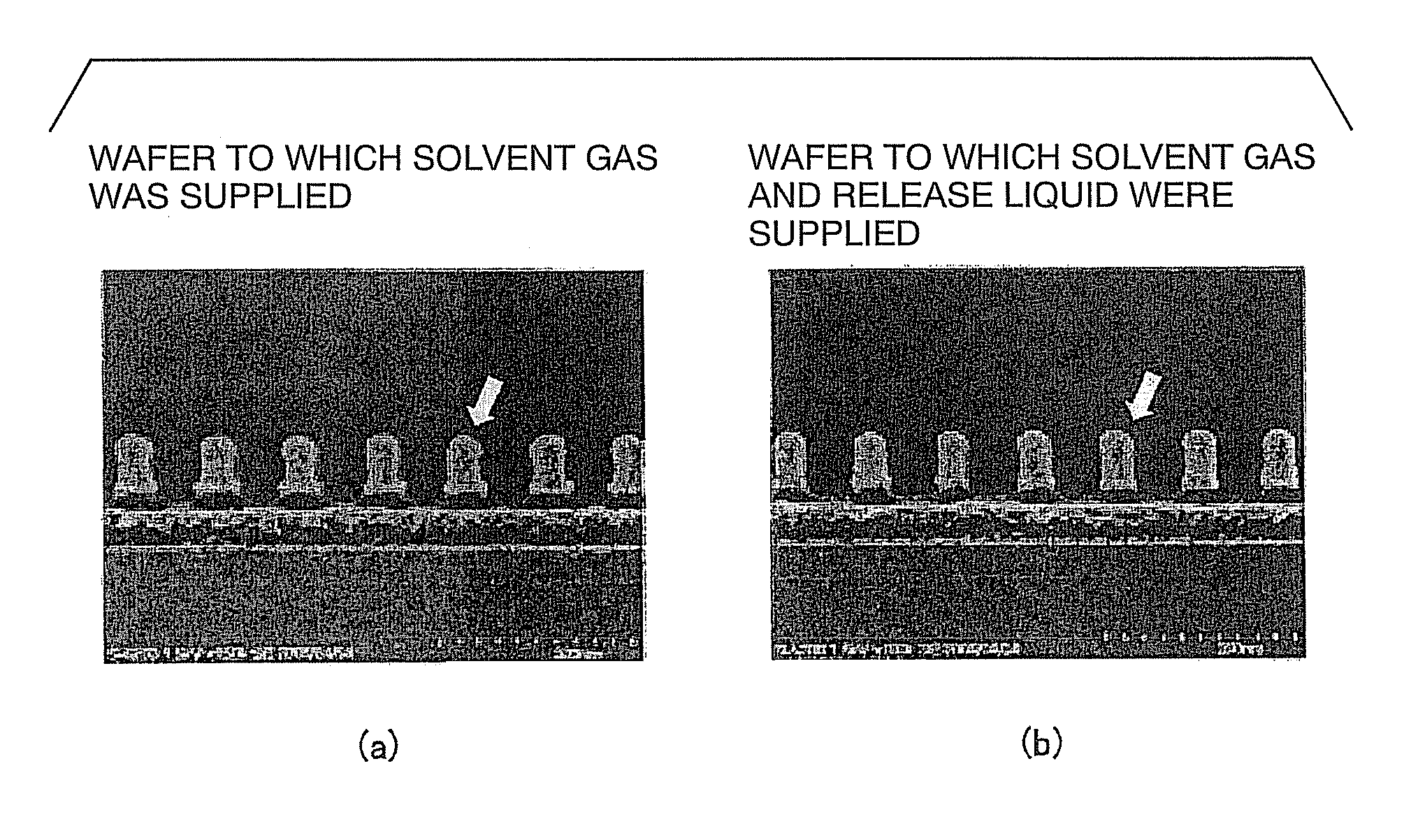
[0078]In Experiment 1, a resist film on a wafer which had been subjected up to the supply of the solvent gas, and a resist film on a wafer which had been subjected up to the supply of the release liquid were compared to each other. FIG. 9 show the result. FIG. 9(a) shows a cross-section of the resist film (a line part of the resist pattern) after the supply of the solvent gas, and FIG. 9(b) shows a cross-section of the resist film (a line part of the resist pattern) after the supply of the release liquid. See, particularly the sectional shapes indicated by the arrows in the drawings. The resist cross-section shown in FIG. 9(a) has a bell-like shape because of the supply of the solvent gas. On the other hand, the resist cross-section shown in FIG. 9(b) after the supply of the release liquid has substantially a rectangular shape, although an upper part thereof is somewhat rounded. Namely, the following facts can be understood. Since the parts dissolved by the solvent gas sagged, the c...

experiment 2

[0079]In Experiment 2, four wafers were prepared, and these wafers were subjected up to the developing process to form resist patterns thereon. At this stage, as a sample for comparison, one wafer was taken out from the resist coating and developing apparatus 1 (this wafer is referred to as “wafer a” for the matter of convenience). Then, one (referred to as “wafer b”) of the rest three wafers was transported to the resist-film processing apparatus 100 and was exposed to the solvent gas. The wafer b was taken out, without any release liquid being supplied thereto. Then, one (wafer c) of the rest two wafers was transported to the resist-film processing apparatus 100. The wafer c was exposed to the solvent gas, and the release liquid was supplied thereto. Then, the wafer c was washed with water, dried, and taken out. The last one wafer (wafer d) was transported to the resist-film processing apparatus 100. Then, the release liquid was supplied to the wafer d, without the wafer d being e...


PUM

PropertyMeasurementUnit
temperatureaaaaaaaaaa
widthaaaaaaaaaa
widthaaaaaaaaaa

Abstract

The present invention provides a resist coating and developing apparatus, a resist coating and developing method, a resist-film processing apparatus, and a resist-film processing method, capable of reducing a line width roughness by planarizing a resist pattern. The resist coating and developing apparatus comprises: a resist-film forming part configured to coat a resist onto a substrate to form a resist film thereon; a resist developing part configured to develop the exposed resist film to obtain a patterned resist film; and a solvent-gas supply part configured to expose the resist film, which has been developed and patterned by the resist developing part, to a first solvent of a gaseous atmosphere having a solubility to the resist film. A solvent supply part supplies, to the resist film which has been exposed to the first solvent, a second solvent in a liquid state having a solubility to the resist film.

Description

BACKGROUND OF THE INVENTION[0001]1. Field of the Invention[0002]The present invention relates to a resist coating and developing apparatus and a resist coating and developing method, which coats a resist onto a substrate and develops an exposed resist film to form a resist pattern. In particular, the present invention relates to a resist coating and developing apparatus, a resist coating and developing method, a resist-film processing apparatus, and a resist-film processing method, capable of reducing a line width roughness by planarizing the resist pattern.[0003]2. Description of Related Art[0004]In order to manufacture a semiconductor circuit having a higher integrity, further miniaturization is desired. For example, a critical dimension (CD) of an etching mask has reached 32 nm or 22 nm which is smaller than an exposure limitation of an existing exposure apparatus. In a case where a channel of such a width of a field-effect transistor (FET) is formed, if a line width roughness (L...

Claims


Application Information

Patent Timeline
Patent Type & Authority Patents(United States)
IPC IPC(8): G03F7/00G03F7/40G03F7/004
CPCG03F7/70341H01L21/6715H01L21/67115H01L21/0274
Inventor INATOMI, YUICHIRO
Owner TOKYO ELECTRON LTD
Learn More