
Magnetic register vent cover and associated method

Inactive Publication Date: 2013-04-16
DILLON KEVIN
View PDF7 Cites 17 Cited by
  • Summary
  • Abstract
  • Description
  • Claims
  • Application Information

AI Technical Summary

Benefits of technology

This patent describes an air register that can be placed in an existing hole in a floor, wall, or ceiling to diffuse air away from an air duct. The register includes a body with interconnected louvers that can be opened and closed to adjust the hot or cold air flow. The register also has two parallel linear travel paths that ensure a secure connection to the air duct and allow for easy adjustment of the air flow. Unlike traditional screw or bolt fasteners, the register remains static without needing additional parts. Overall, this invention provides a simple and effective solution for diffusing air in a variety of settings.

Problems solved by technology

The positioning of registers in rooms is made more difficult by dual-purpose heating and air conditioning systems.
Such threaded fasteners, even when countersunk, greatly detract from the smooth planar design of the register vent's outer surface.
Furthermore, user of threaded fasteners weakens the structural integrity where they are inserted into the support surface.
As such, there is an increased risk for mechanical failure in the areas around a register vent.
Unfortunately, this prior art reference does not disclose a means of securing the register by way of magnetically affixing it to the existing air duct in order to permit a smooth outer surface of the register, free of raised fasteners.
Unfortunately, this prior art reference does not disclose a means for permitting and adjusting the flow of air through building conduits for purposes of adjusting room temperatures, and would not be easily adapted to be employed for such purposes.
Unfortunately, this magnetic panel is employed to stop air flow and is not designed for holding the register in place while a user adjusts the amount of air permitted to flow out thereof.

Method used


Image

  • Magnetic register vent cover and associated method
  • Magnetic register vent cover and associated method
  • Magnetic register vent cover and associated method

Examples


Embodiment Construction

[0031]The present invention will now be described more fully hereinafter with reference to the accompanying drawings, in which a preferred embodiment of the invention is shown. This invention may, however, be embodied in many different forms and should not be construed as limited to the embodiment set forth herein. Rather, this embodiment is provided so that this application will be thorough and complete, and will fully convey the true scope of the invention to those skilled in the art. Like numbers refer to like elements throughout the figures.

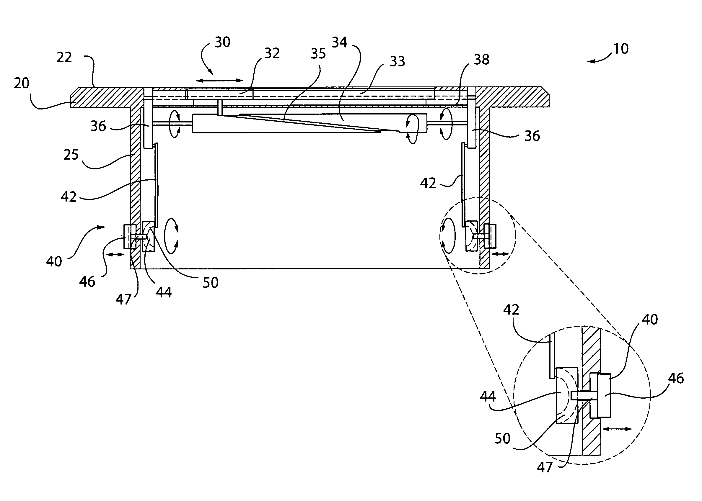
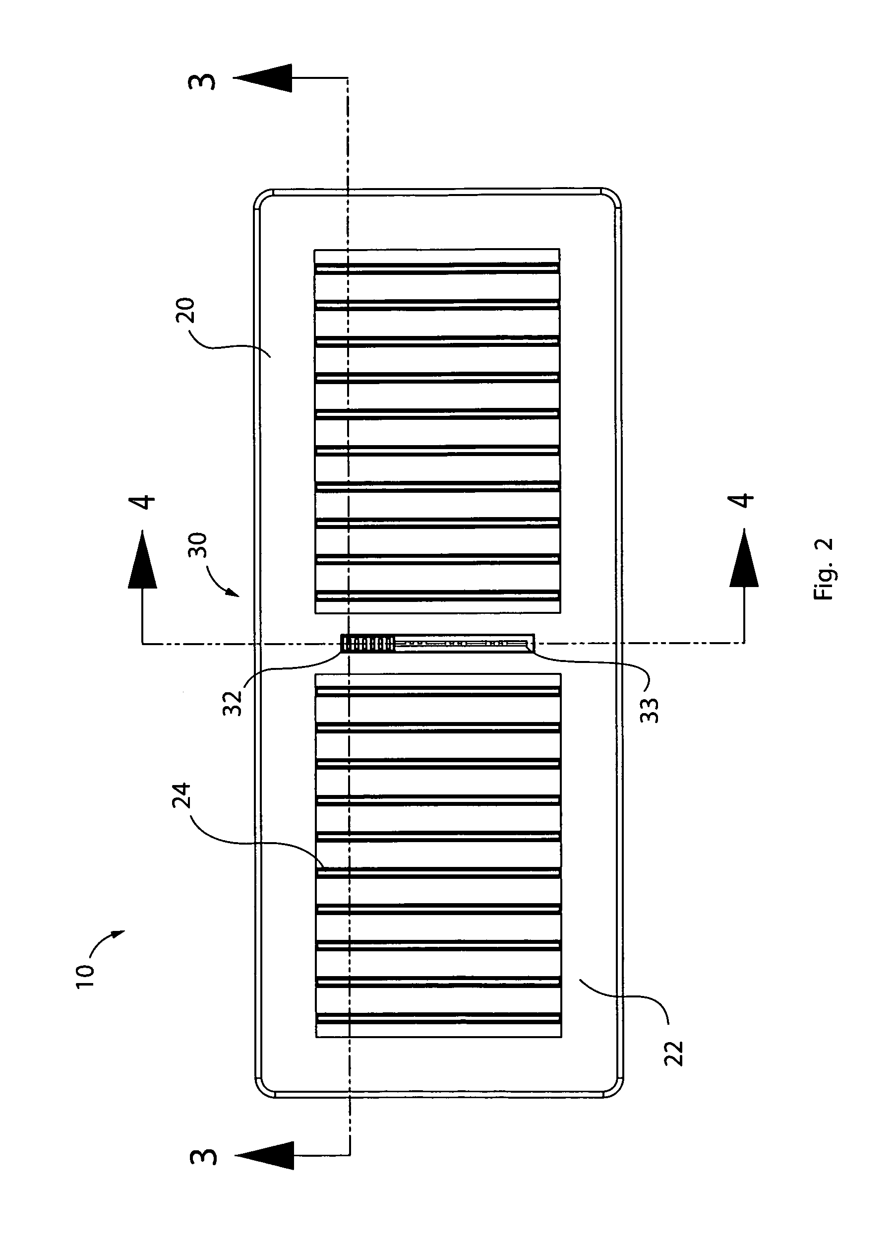
[0032]The apparatus of this invention is referred to generally in FIGS. 1-4 by the reference numeral 10 and is intended to provide an air register. It should be understood that the air register 10 may be used to cover and adjust the air flow out of many different types, sizes, and shapes of ductwork openings, and may be designed to be used in both residential and commercial settings.

[0033]Referring to FIGS. 1-4 initially, an air register 10 f...


PUM


Abstract

An air register for diffusing air away from an existing air duct may include a body with an open panel and plurality of louvers situated therealong. The body may include a plurality of planar side walls extending orthogonally to the panel and disposed inwardly from an outer perimeter thereof. A mechanism may be included for articulating the interconnected louvers between open and closed positions. A second mechanism may be included for magnetically affixing the planar walls to the existing air duct. In operation, the magnetically affixing mechanism may be automatically displaced outwardly and away from the planar side walls while the interconnected louvers biasing mechanism is toggled between the open and closed positions. In this manner, the body may be maintained at a substantially stable position during articulation of the interconnected louvers by maintaining the magnets firmly against the walls of the air duct.

Description

CROSS REFERENCE TO RELATED APPLICATIONS[0001]This application claims the benefit of U.S. Provisional Application No. 61 / 011,222, filed Jan. 17, 2008, the entire disclosures of which are incorporated herein by reference.STATEMENT REGARDING FEDERALLY SPONSORED RESEARCH OR DEVELOPMENT[0002]Not Applicable.REFERENCE TO A MICROFICHE APPENDIX[0003]Not Applicable.BACKGROUND OF THE INVENTION[0004]1. Technical Field[0005]This invention relates to air duct registers and, more particularly, to a magnetically affixed air duct register for diffusing air away from an existing air duct.[0006]2. Prior Art[0007]Forced air heating and cooling systems provide an economical and quick reaction to desired temperature changes in a structure. Forced air systems are used in winter for heating by blowing air around a fire box, which may be fueled by gas, oil or coal, or around an electrical or fluid heat source, and then blowing the air through a register and through sealed ducts along floors and wall, and th...

Claims


Application Information

Patent Timeline
IPC IPC(8): F24F7/00
CPCF24F13/084F24F13/12
Inventor DILLON, KEVIN
Owner DILLON KEVIN
Learn More