Slide fastener and hidden slide fastener
A zipper and sprocket technology, applied in fabrics, textiles, clothing, etc., can solve problems such as difficult to prevent warp misalignment, broken chain belts, and zippers that cannot withstand long-term use
- Summary
- Abstract
- Description
- Claims
- Application Information
AI Technical Summary
Problems solved by technology
Method used
Image
Examples
Embodiment 1
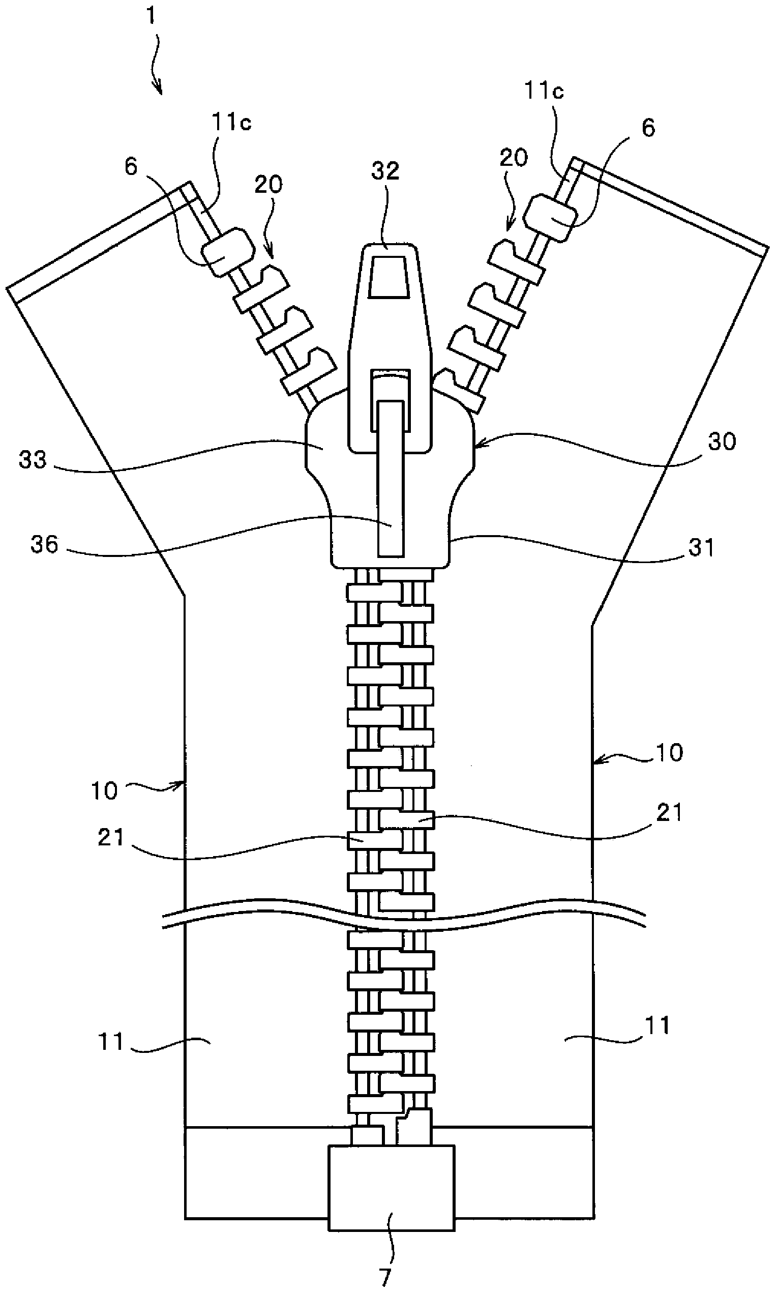
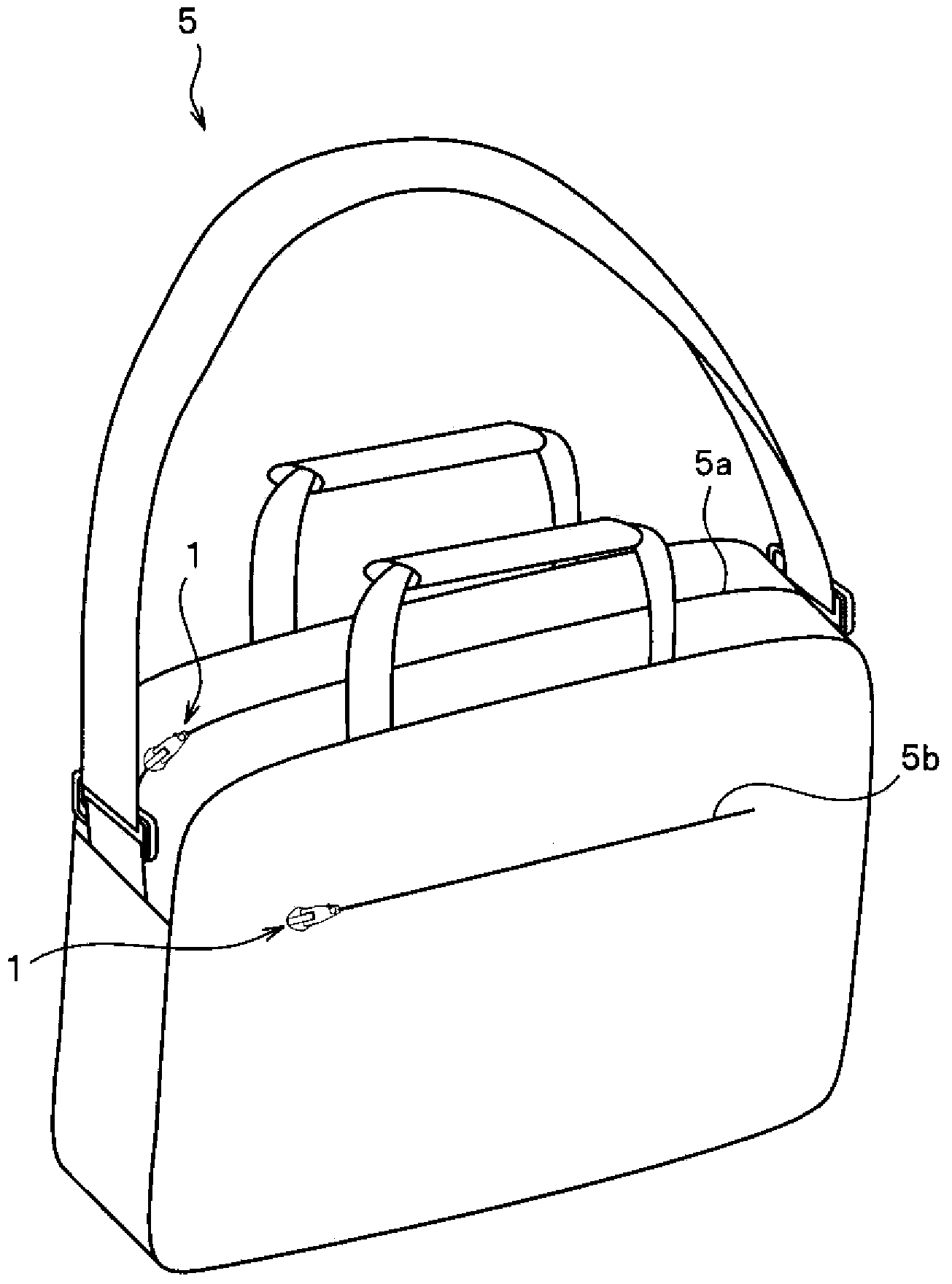
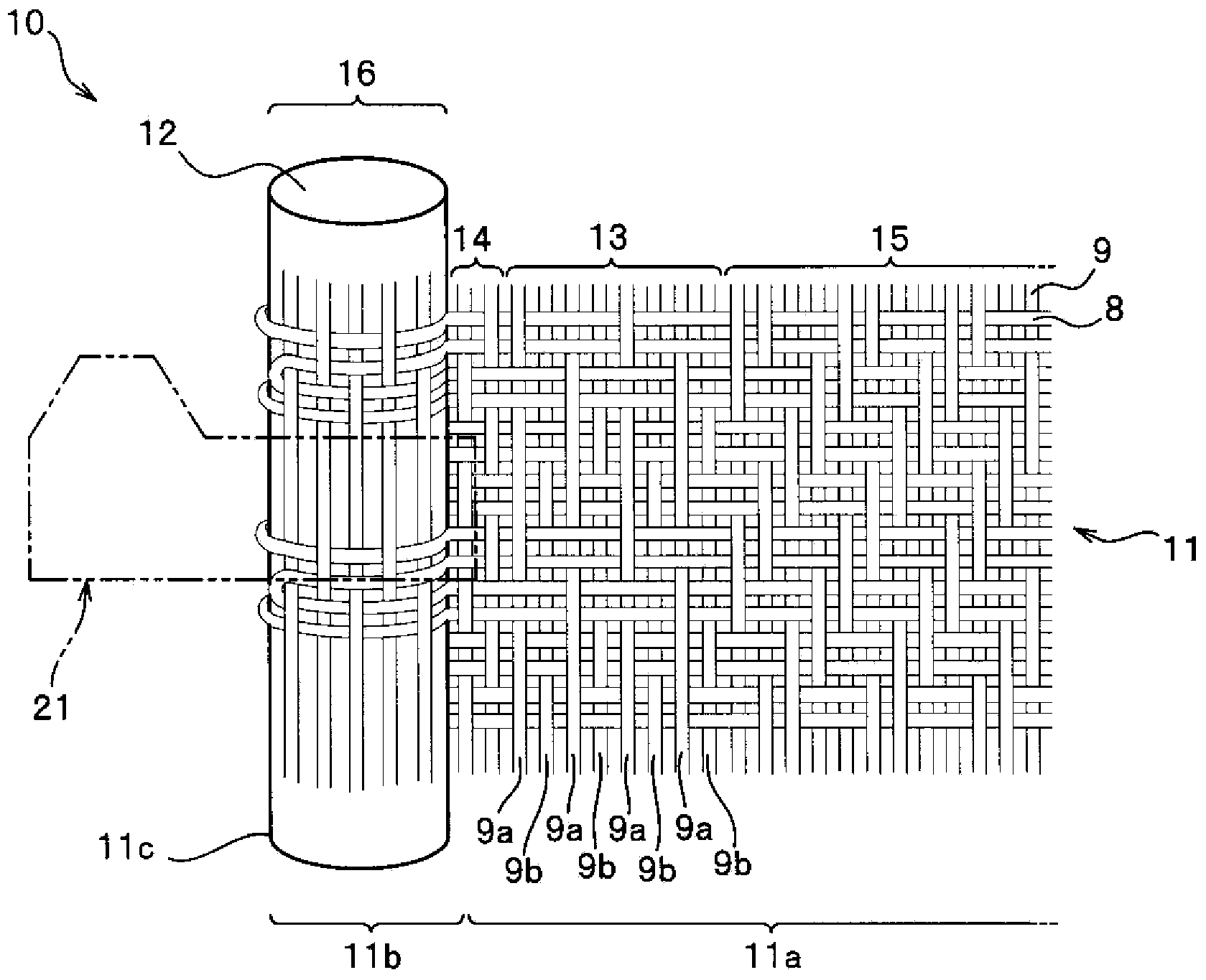
[0092] figure 1 is a schematic diagram showing the slide fastener of the present embodiment 1, figure 2 It is a perspective view showing the bag using the zipper. also, image 3 It is a structure diagram which schematically shows the knitting structure of a part of the fastener tape. and, Figure 4 is a cross-sectional view of the zipper.
[0093] In addition, in the following description, the front-back direction means the longitudinal direction of a fastener tape, and is the same direction as the sliding direction of a slider slide. In particular, the direction in which the slider slides so that the left and right zipper elements mesh to close the zipper is defined as the front, and the direction in which the slider slides so that the left and right zipper elements are separated to open the zipper is defined as the rear. .
[0094] In addition, the left-right direction means the width direction of the fastener tape, and is a direction parallel to the tape surface of ...
Embodiment 2
[0143] Figure 11 It is a main part cross-sectional view enlargedly showing the main part of the slide fastener of this Example 2.
[0144] The slide fastener 2 of the present embodiment 2 is constituted as a usual type of slide fastener, and it has a pair of fastener stringers 40 in which spiral fastener elements 51 are sewn along the belt inner edges where the left and right fastener tapes 41 face each other. The unshown first stopper and second stopper at the front end and the rear end of each fastener chain 40 , and the puller disposed so as to be slidable along the continuous element rows of the fastener chain 40 . Head 60.
[0145] Here, in the slide fastener 2 of this Example 2, the fastener element 51 has the structure similar to the conventional spiral fastener element, and the 1st stopper, the 2nd stopper, and the slider 60 have the same structure as a conventional spiral fastener element. The conventional 1st stopper, the 2nd stopper, and the slider used for the s...
Embodiment 3
[0156] Figure 12 It is a sectional view which shows the invisible slide fastener of this Example 3.
[0157] The concealed slide fastener 3 of the third embodiment has a pair of concealed type fastener chains 70, a first stopper and a second stopper (not shown) arranged at the front end and the rear end of each fastener chain 70 , and the slider 90 arranged so as to be slidable along the continuous element row of the fastener chain 70 .
[0158] The concealed type fastener chain 70 of the present embodiment 3 has a chain belt 71 and a continuous chain element row arranged along the chain element mounting portion 71c of the chain belt 71. A belt bending portion 71b extending from one side edge and bent into a letter U shape, and a chain tooth mounting portion 71c further extending from the belt bending portion 71b.
[0159] The continuous element row is formed by sewing the helical zipper element 81 on the fastener tape 71 with a multi-thread chain stitch of sewing thread 87...
PUM
 Abstract
Description
Claims
Application Information
 - R&D Engineer
- R&D Manager
- IP Professional
- Industry Leading Data Capabilities
- Powerful AI technology
- Patent DNA Extraction
Browse by: Latest US Patents, China's latest patents, Technical Efficacy Thesaurus, Application Domain, Technology Topic, Popular Technical Reports.
© 2024 PatSnap. All rights reserved.Legal|Privacy policy|Modern Slavery Act Transparency Statement|Sitemap|About US| Contact US: help@patsnap.com


