
Signals communication apparatus

a communication apparatus and signal technology, applied in the field of signal communication apparatus and methods, can solve the problems of cumbersome optocouplers, degrading performance, and affecting cost and overall volume, and achieve the effect of significantly reducing power consumption and reducing data exchanges

Active Publication Date: 2013-04-09
STMICROELECTRONICS SRL
View PDF14 Cites 0 Cited by
  • Summary
  • Abstract
  • Description
  • Claims
  • Application Information

AI Technical Summary

Benefits of technology

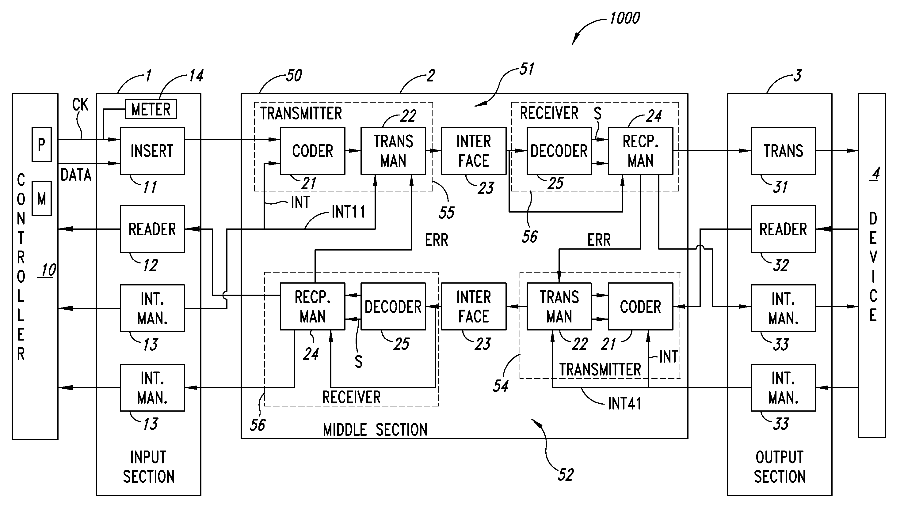
The patent describes a device that allows for fast and reliable data transmission through a wirelessly isolated channel. It uses a communication protocol that reduces data exchanges and power consumption between devices with isolated interfaces.

Problems solved by technology

For transmitting signals, a typical solution is to use optocouplers which are however cumbersome and have performances degrading over time.
The insertion of a structure as described in the aforementioned patent publication highly affects the costs and the overall volume.

Method used


Image

  • Signals communication apparatus
  • Signals communication apparatus
  • Signals communication apparatus

Examples


Embodiment Construction

[0020]In the following description, numerous specific details are given to provide a thorough understanding of embodiments. The embodiments can be practiced without one or more of the specific details, or with other methods, components, materials, etc. In other instances, well-known structures, materials, or operations, such as, for example, decoders and encoders, are not shown or described in detail to avoid obscuring aspects of the embodiments.

[0021]Reference throughout this specification to “one embodiment” or “an embodiment” means that a particular feature, structure, or characteristic described in connection with the embodiment is included in at least one embodiment. Thus, the appearances of the phrases “in one embodiment”“according to an embodiment” or “in an embodiment” and similar phrases in various places throughout this specification are not necessarily all referring to the same embodiment. Furthermore, the particular features, structures, or characteristics may be combine...


PUM


Abstract

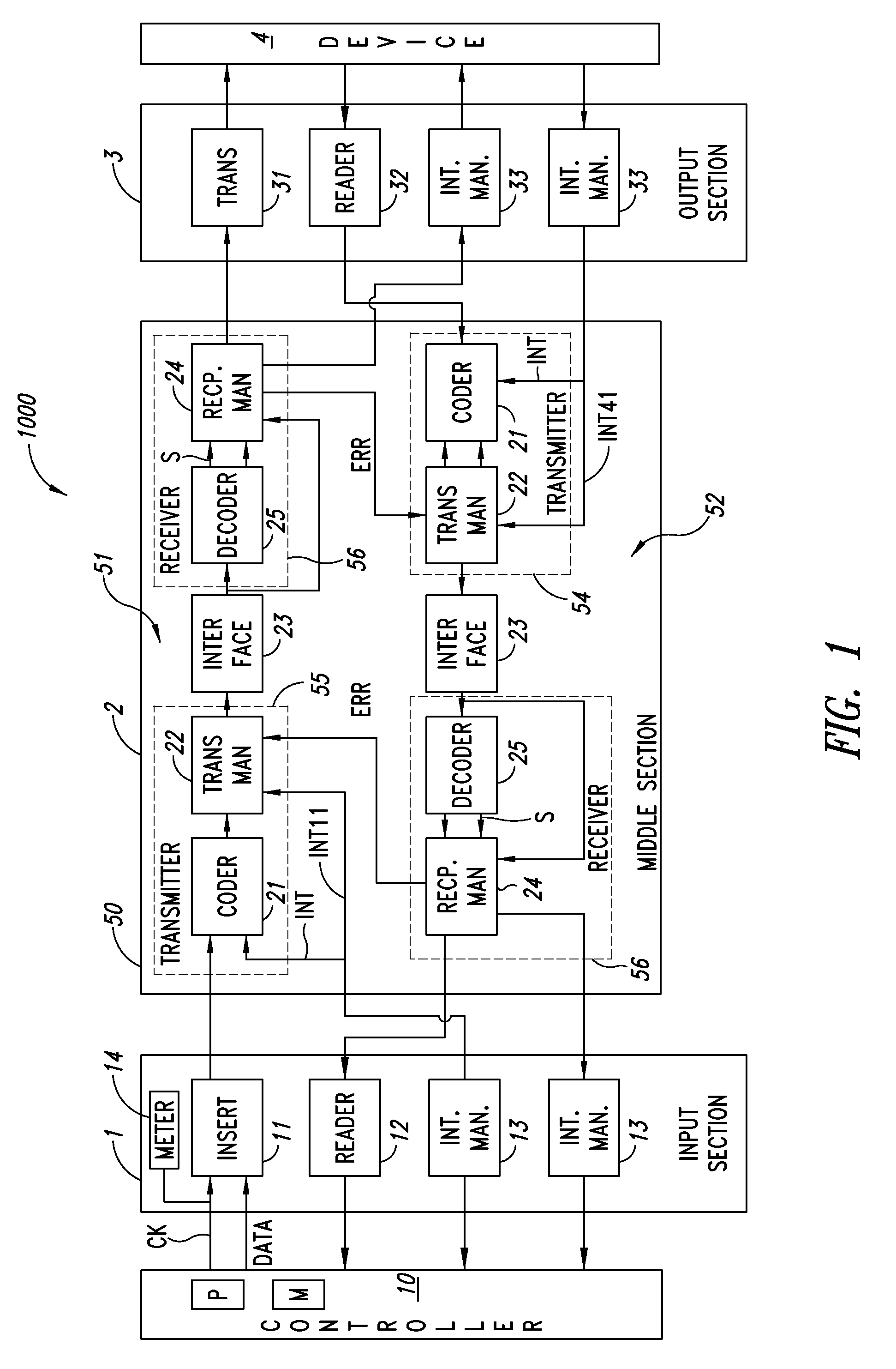
A signal communication apparatus comprising first and second channels for communicating signals between two electronic devices; each of said first and second channels has a transmitter for transmitting signals, a receiver for receiving signals and an interface arranged between the transmitter and the receiver. The transmitters code the signals in the form of a frame of H bits, with H being an integer, and adapted to serially transmit said frame of H bits through said interface, and the receivers decode the frames of H bits, a frame of H bits having P data bits, K redundancy bits and a sequence of L control bits adapted to identify the type of frame to be transmitted, with L, P and K being integers.

Description

BACKGROUND[0001]1. Technical Field[0002]The present disclosure relates to signal communication apparatus and methods.[0003]2. Description of the Related Art[0004]Applications for communicating circuits operating at high power voltages (even hundreds of volts) with circuits rather operating at low power voltages are known, in which there exists a galvanic isolation which increases the safety of the user who comes in contact with the low voltage interface.[0005]Typically, the applications using such isolation are those related to the power suppliers which are to be directly connected to the mains, as well as the industrial applications in which driving loads at high voltages occurs.[0006]A typical example are the “high side switch drivers”, in which driving switches feed inductive loads by means of high voltages. In such a case, the potential differences that may dynamically develop between the low voltage part and the high voltage part may also reach thousands of volts per microsecon...

Claims


Application Information

Patent Timeline
Patent Type & Authority Patents(United States)
IPC IPC(8): H04B1/44H04B1/38H04J3/16H04W4/00
CPCH04L1/1896H04L1/1812
Inventor LOMBARDO, GIOVANNIGIOMBANCO, SALVATORETUMMINARO, SALVATOREMARINO, FILIPPO
Owner STMICROELECTRONICS SRL
Learn More