
Verification plans to merging design verification metrics

a technology of design verification and verification plans, applied in the direction of cad circuit design, program control, instruments, etc., can solve the problems of not being able to exercise all logic, the task of verification may be trivial, and the verification becomes significantly difficult, so as to achieve accurate progress measurement, more flexible control over the model merge operation, and accurate progress measurement

Active Publication Date: 2013-04-02
CADENCE DESIGN SYST INC
View PDF20 Cites 48 Cited by
  • Summary
  • Abstract
  • Description
  • Claims
  • Application Information

AI Technical Summary

Benefits of technology

The present invention provides methods and a computing apparatus that enable more flexible control over the model merge operation. This makes accurate progress measurement feasible even when different verification environments and different levels of DUT integration are involved. The invention allows the user to keep separate model and data elements that should not be merged, define additional user-specified merge operations that would not occur automatically, and drive the automatic merge process based on selected instances rather than selected modules. It also provides a uniform approach for controlling the merge process that applies equally to different languages and hierarchies.

Problems solved by technology

In smaller designs the task of verification may be trivial, but as digital design complexity increases verification becomes significantly difficult.
In most digital designs suited for commercial applications, there may be no possibility of exercising all logic.
If verification suite involves multiple verification environments and / or multiple levels of design integration, the resulting models are potentially difficult to merge in a meaningful way, because the structures do not correspond intuitively, and because information that should be kept separate gets merged automatically.
This makes it very difficult, and in some cases impossible, to accurately measure the overall progress of verification.
With this approach, if such coverage groups are part of a verification intellectual property (VIP) block, results of two VIP instances will be merged, even if such a merge is undesirable (e.g., if the test benches verify two different designs, or two different aspects of the same design).
A limitation with all existing approaches is the inability to separate coverage and check metrics from different verification environments during the verification progress measurement.
However, such code changes break the VIP reuse concept.
Furthermore, the methods provided for the user to control verification model merging are complex to use.
Also, the current approaches do not provide a sensible solution for module-to-system result merging since one ‘covdut’ cannot include another ‘covdut’ within its hierarchy.
If a verification IP or design IP block is instantiated more than once in a verification model, the user is not able to control the type-based merging of coverage / check results.
Because of this, obtaining accurate verification results for IC designs is a challenge when VIP blocks are used.
These methods can be very processor intensive and may typically be performed on multiple machines in parallel.
These approaches experience significant difficulties as the design matures.
However, the potential for a uniform approach is undermined by the fact that different tools process assertions in different ways.
Also, while assertion languages define clearly what a single assertion means in one run of a design, accumulation of assertion results across multiple runs in a regression suite is not straightforward, especially when regression suites include error handling tests in which assertion-triggering errors are intentionally injected into the design.
These challenges make it difficult to incorporate assertion results into a verification plan in a manner that addresses both correctness checking and completeness checking consistently across multiple tools and multiple runs.
At a more detailed level, functional verification of a design quickly becomes much more complex.
Functional verification also becomes more complex due to the sheer size of today's designs, which are often too complex to verify in a single environment, but rather must be decomposed hierarchically into a set of verification tasks, the results of which must be recomposed (i.e., merged) carefully to determine whether or when the entire design has been verified.
Another source of verification complexity is the fact that different verification tools and algorithms are available, and depending upon the nature of a particular sub-task in a complex verification flow, one tool or another may be preferable for that sub-task.
The fact that each algorithm provides slightly different results adds to the complexity of recomposing the results of the various subtasks into an intelligible result for the whole design.
Third, provided methods employ a mechanism for explicit user-directed recomposition of verification results, for cases in which the complexity of the verification problem makes the automatic recomposition mechanism insufficient.
However, this simple model may not be sufficient for more focused verification approaches involving individual tests aimed at specific scenarios, especially those that involve verification of error handling capabilities.
If an assertion with a MustNotFail checkintent attribute fails, then the entire run fails.
Being based on Explored, additional complexity is added to the algorithms.
Doing so results in “failed” being used for both simulation (FailedCount) and formal analysis (Failed) results.

Method used


Image

  • Verification plans to merging design verification metrics
  • Verification plans to merging design verification metrics
  • Verification plans to merging design verification metrics

Examples


##s example ahb vips

SRS Example AHB VIPs

[0307]FIG. 16 illustrates an exemplary verification intellectual property (VIP) module, an advanced high performance bus (AHB) verification intellectual property (VIP) module, and its form of requirements when instantiated in an integrated circuit. FIG. 16 shows a first test bench (TB#1) for Module Verification and a second test bench (TB#2) for System Verification. The user has a number of goals in mind with respect to these test benches. The coverage and check results from the AHB VIP instances in the first test bench TB#1 and TB#2 shall be separated with no type based results being planned. Another goal is that the coverage results for the UART in the first test bench TB#1 and the coverage results for the first UART (UART#1) in the second test bench TB#2 shall be merged together.

[0308]FIG. 17 illustrates a hierarchical representation of the two runs for verification of the first and second test benches shown in FIG. 16.

Using Verification Scopes, Named Subtrees...

example 1

[0353]

test test1 {verification_scope: VS1;named_subtree: NST1: “dut.ctrl1.arb1”;...}test test2 {verification_scope: VS2;named_subtree: NST2: “sys.master1.ctrl1.arb1”;...}

[0354]Example 1 defines two tests, test1 and test2. The test container for each test defines a verification scope and a named subtree. The test test1 defines verification scope VS1 and gets associated with it and defines a named subtree NST1 with hierarchical instance path “dut.ctrl1.arb1” as the root of the named subtree. Similarly, test test2 defines verification scope VS2 and gets associated with it, and defines a named subtree NST2 with hierarchical instance path “sys.master1.ctrl1.arb1” as the root of the named subtree.

[0355]Additionally, test1 has a default named subtree associated with it. The default named subtree had id “dut” and is rooted at “dut”. Similarly, test2 has a default named subtree with id “sys” and rooted at “sys”, associated with it.

[0356]Consider a second example specification of named subtre...

example 2

[0357]

group A {named_subtree: CMNST: “dut.a”;test test1 {named_subtree: NST1: “dut.ctrl1.arb1”;...}test test2 {named_subtree: NST2: “dut.ctrl1.counter1”;...}...}

[0358]In Example 2, the two tests have a named subtree defined each. In addition each test has a default named subtree with id “dut” rooted at “dut”. The group specific named subtree “CMNST” is also another subtree associated with each of the two tests. Thus, each test has three named subtrees associated with it.

Error Reporting:

[0359]Invalid hierarchy specified as subtree root: An error is reported by the verification manager (VM) if an invalid hierarchy node is specified as subtree root. This is reported in the verification manager (VM) console at the time of analysis.[0360]Same subtree name for two nodes in the same run: An error is reported by the verification manager (VM) if the same subtree name is specified for two nodes in the same run.[0361]Same subtree name for parent and child: An error is reported by the verificat...


PUM


Abstract

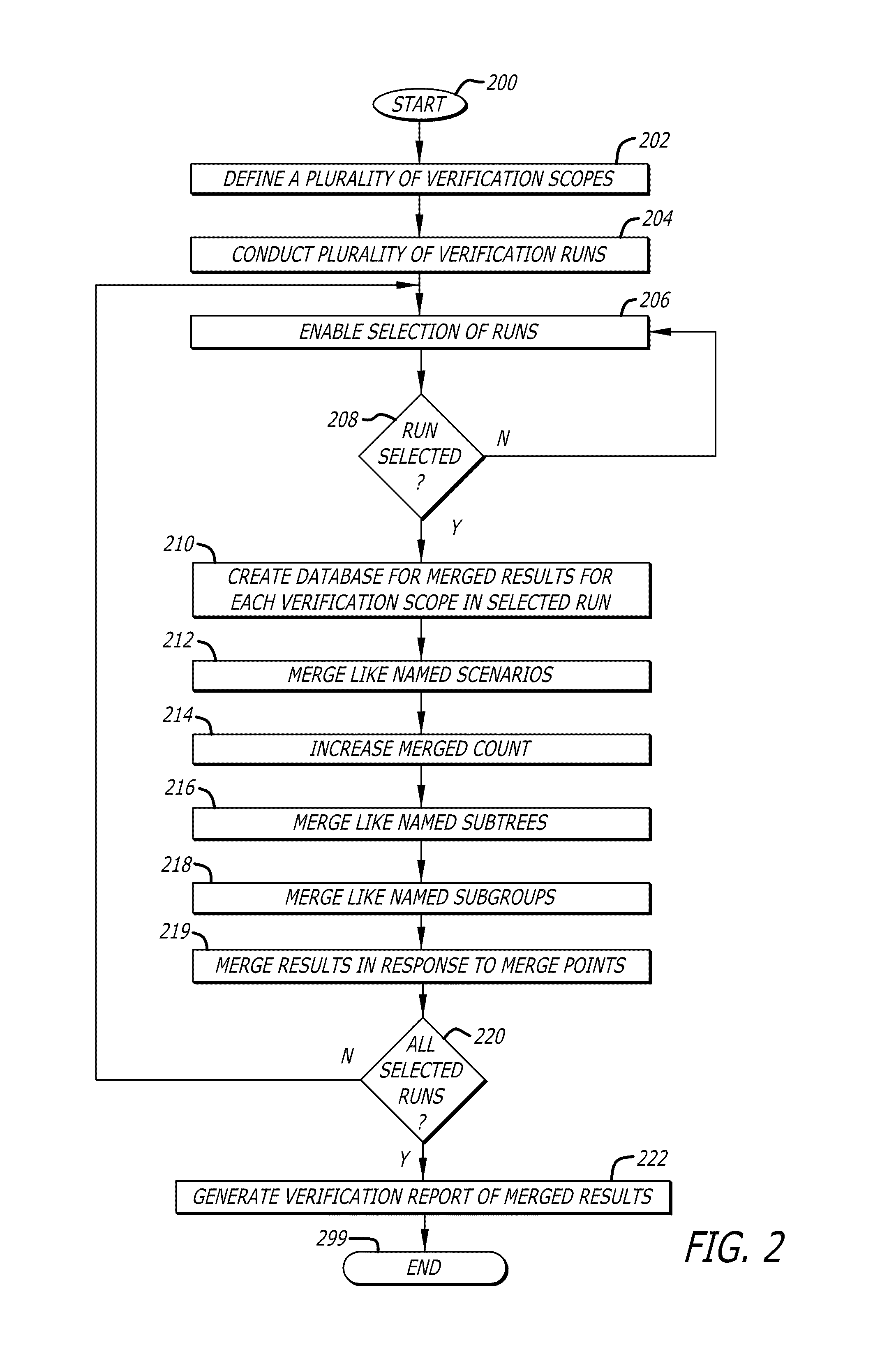
A method and apparatus for producing a verification of digital circuits are provided. In an exemplary embodiment on the invention, a plurality of verification scopes of an integrated circuit design as defined as part of a verification plan. A plurality of verification runs are executed within two or more verification scopes defined by the verification plan. At least two verification runs are selected to merge verification results together. Like named scenarios are merged together for each verification scope to generate merged verification results that are then stored into a merge database. A verification report is generated for the integrated circuit design from the merged verification results. A merge point may be specified so like named subtrees and subgroups may be merged across different verification scopes of selected verification runs. The merge point may combine check and coverage results obtained during simulation with check and coverage results obtained during formal verification.

Description

CROSS REFERENCE TO RELATED APPLICATIONS[0001]This patent application incorporates by reference and claims the benefit of U.S. Provisional Patent Application No. 61 / 156,479 entitled MERGING OF DESIGN VERIFICATION METRICS filed on Feb. 28, 2009 by inventors Sandeep Pagey et al, which is hereby incorporated by reference in its entirety; and U.S. Provisional Patent Application No. 61 / 046,372 entitled USER- AND PLAN-DRIVEN MERGING OF DESIGN VERIFICATION METRICS ACROSS MULTIPLE HIERARCHIES AND DESIGN INTEGRATION LEVELS filed on Apr. 18, 2008 by inventors Erich Marschner et al.[0002]Furthermore, the subject matter of the present invention is a continuation in part and claims the benefit of U.S. patent application Ser. No. 11 / 759,758, entitled METHODS AND APPARATUS FOR MERGING COVERAGE FOR MULTIPLE VERIFICATION AND DESIGN SCENARIOS, filed Jun. 7, 2007, by Bijaya Sahu et al., now issued as U.S. Pat. No. 7,890,902, which is hereby incorporated by reference in its entirety.FIELD OF THE INVENTI...

Claims


Application Information

Patent Timeline
Patent Type & Authority Patents(United States)
IPC IPC(8): G06F17/50
CPCG06F17/5022G06F17/504G01R31/2848G06F30/33G06F30/3323
Inventor ARMBRUSTER, FRANKPAGEY, SANDEEPMARSCHNER, F. ERICHLEIBOVICH, DANJAIN, ALOKSCHERER, AXELPERI-GLASS, YARON
Owner CADENCE DESIGN SYST INC
Learn More