
Semiconductor device having a grain orientation layer

a technology of semiconductors and grains, applied in the manufacturing of semiconductor/solid-state devices, solid-state devices, electric devices, etc., can solve the problems of thinning the conductor line, failure of the integrated circuit, and undesirable formation of copper oxide on the planarized copper or copper-based surface, and achieve the effect of less random grain orientation in the metal features

Inactive Publication Date: 2013-03-26
ALSEPHINA INNOVATIONS INC
View PDF36 Cites 5 Cited by
  • Summary
  • Abstract
  • Description
  • Claims
  • Application Information

AI Technical Summary

Benefits of technology

This patent is about a technique for improving metal features in a metallization layer by aligning grains in the metal using a grain orientation layer and annealing. This results in a larger number of metal grains with a preferred grain orientation, which makes the metal more uniform and reliable. This technique can be used to create more organized and efficient metal structures in microelectronic devices.

Problems solved by technology

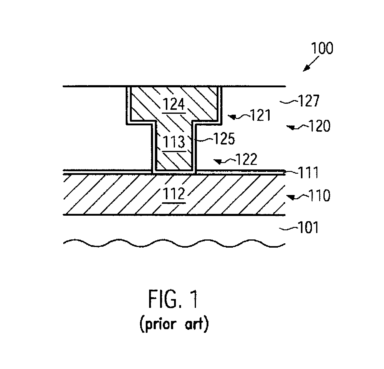
A drawback associated with the use of copper or copper-based metallurgy for metallization processes of semiconductor devices, e.g., back-end metallization processes, results from the undesirable formation of copper oxide on the planarized copper or copper-based surfaces of the inlaid metallization features as a result of oxidation, e.g., due to the strong chemical oxidizing agents conventionally included in CMP slurries for enhancing copper dissolution / removal rates or as a result of exposure of the freshly abraded copper-based surfaces to an oxidizing atmosphere, for instance, air or oxygen.
As a consequence of the momentum transfer and the thermally enhanced mobility, metal atoms and / or ions diffuse in the direction of the current flow and metal loss at the source end of the conductor eventually results in thinning of the conductor line.
The electromigration effect may continue until the conductor line becomes so thin that it separates from the current input and forms an open circuit, resulting in failure of the integrated circuit.
As this usually occurs over an extended period of operation, the failure is often seen by the end user.

Method used


Image

  • Semiconductor device having a grain orientation layer
  • Semiconductor device having a grain orientation layer
  • Semiconductor device having a grain orientation layer

Examples


Embodiment Construction

[0029]Various illustrative embodiments of the invention are described below. In the interest of clarity, not all features of an actual implementation are described in this specification. It will of course be appreciated that in the development of any such actual embodiment, numerous implementation-specific decisions must be made to achieve the developers' specific goals, such as compliance with system-related and business-related constraints, which will vary from one implementation to another. Moreover, it will be appreciated that such a development effort might be complex and time-consuming, but would nevertheless be a routine undertaking for those of ordinary skill in the art having the benefit of this disclosure.

[0030]The present subject matter will now be described with reference to the attached figures. Various structures, systems and devices are schematically depicted in the drawings for purposes of explanation only and so as to not obscure the present disclosure with details ...


PUM

PropertyMeasurementUnit
relative permittivityaaaaaaaaaa
gate lengthaaaaaaaaaa

Abstract

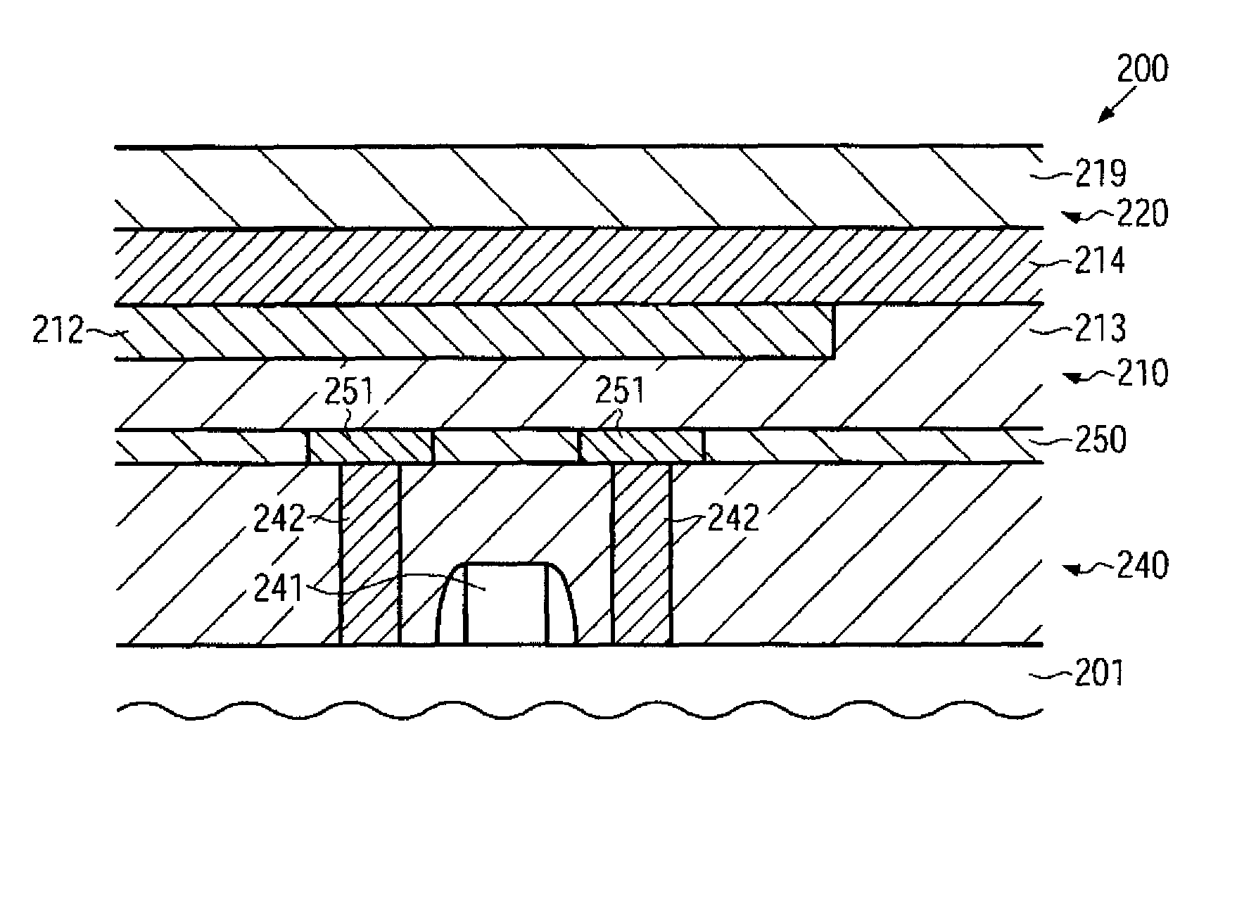
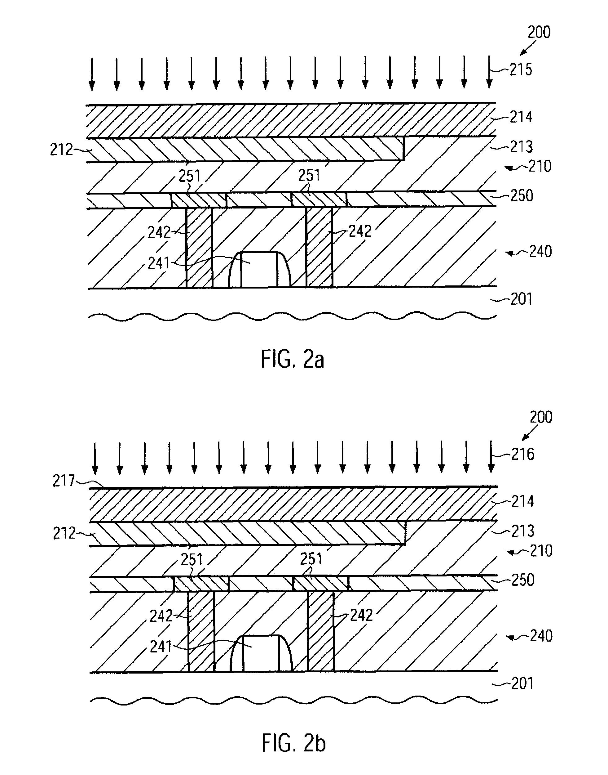
A manufacturing process of a semiconductor device includes generating a less random grain orientation distribution in metal features of a semiconductor device by employing a grain orientation layer. The less random grain orientation, e.g., a grain orientation distribution which has a higher percentage of grains that have a predetermined grain orientation, may lead to improved reliability of the metal features. The grain orientation layer may be deposited on the metal features wherein the desired grain structure of the metal features may be obtained by a subsequent annealing process, during which the metal feature is in contact with the grain orientation layer.

Description

BACKGROUND OF THE INVENTION[0001]1. Field of the Invention[0002]The present invention generally relates to the formation of integrated circuits, and, more particularly, to the fabrication of highly conductive metal features.[0003]2. Description of the Related Art[0004]In modern integrated circuits, a high number of individual circuit elements, such as transistors, capacitors, resistors and the like, are formed in and on an appropriate substrate, typically in a substantially planar arrangement. The electrical connections between the circuit elements may not be provided within the same level, as the number of connections is usually significantly higher than the number of circuit elements. Consequently, one or more wiring levels or layers are provided which include the metal lines and metal regions establishing the electrical connections within a specified level (considered as inner-level connections) and the vias connecting metal lines or regions in different levels (considered as int...

Claims


Application Information

Patent Timeline
Patent Type & Authority Patents(United States)
IPC IPC(8): H01L21/44
CPCH01L21/321H01L21/76834H01L21/76849H01L21/76883H01L21/76886
Inventor BOEMMELS, JUERGENLEHR, MATTHIASRICHTER, RALF
Owner ALSEPHINA INNOVATIONS INC
Learn More