Reflective projection screen having multi-incedent angle
a projection screen and multi-instance technology, applied in the field of projection screens, to achieve the effect of reducing the projection distance, dramatically reducing the installation area, and reducing the appearance of hot spots
- Summary
- Abstract
- Description
- Claims
- Application Information
AI Technical Summary
Benefits of technology
Problems solved by technology
Method used
Image
Examples
example 1
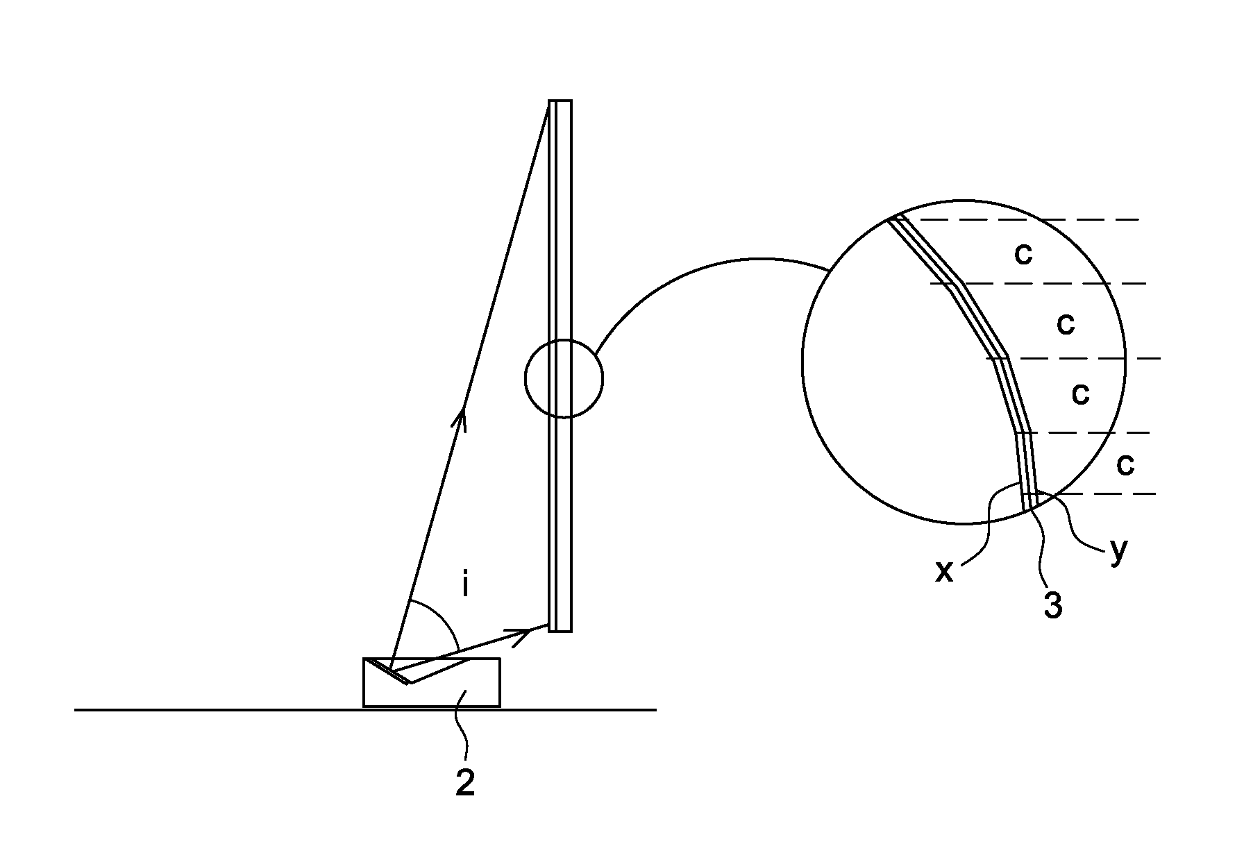
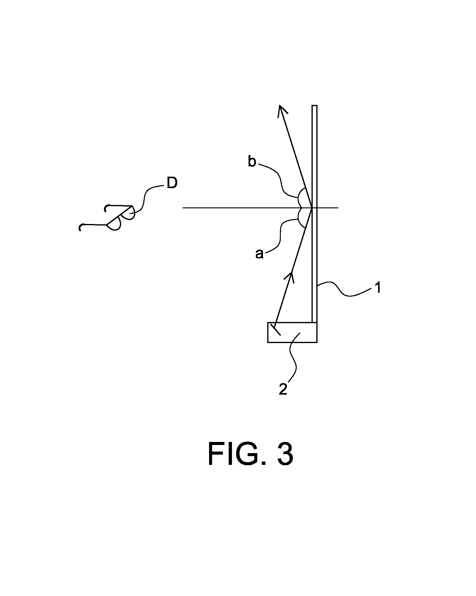
[0056]As shown in FIG. 8, the height h of the reflective screen 1 is 1240 mm which is derived from the lateral length×height of a picture ratio of 16:9 for use with a typical HD TV and thus has a diagonal of 2540 mm (100″) and a lateral length of 2210 mm and the height of 1240 mm. Accordingly, the height h of the reflective screen 1 is equal to 1240 mm. When the lower part of the reflective screen 1 is arranged about 5° above the height h of the short focal point projector 2, the maximum height of the reflective screen 1 equals to 1300 mm, which is derived from 1240 mm plus 60 mm. Additionally, when the projection distance f of 100″ of the short focal point projector 2 is 500 mm, a projection range i which is projected on the reflective screen with the short focal point projector 2 equals to tan ∠=screen height h / projection distance of short focal point and thus the projection angle at the top end of the reflective screen 1 equals to 70° and the projection range i is 65° between 5° ...
example 2
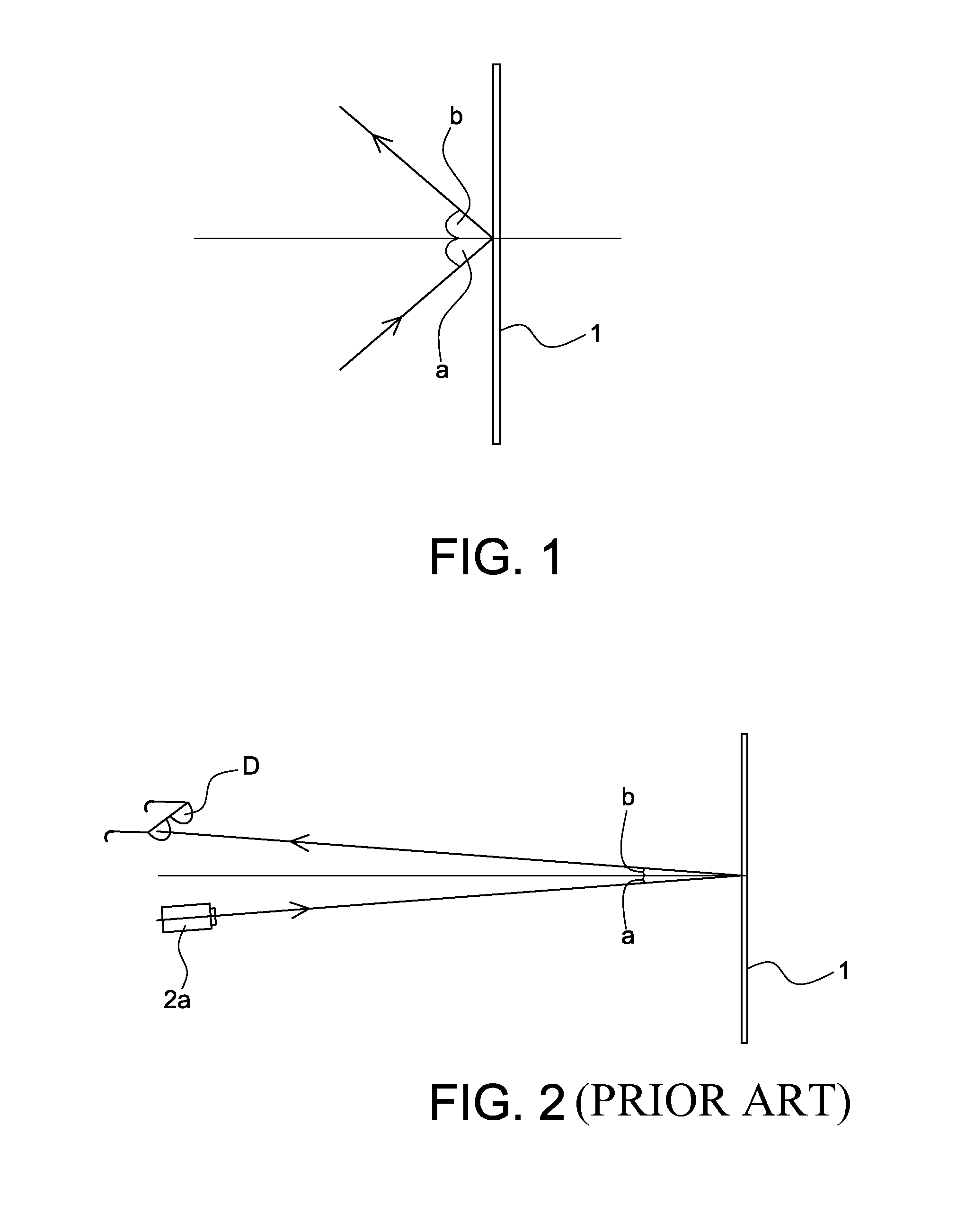
[0065]When the line of the reflective surface c is configured in the manners as described above such that as shown in FIG. 12, where the lines are arranged left to right horizontally, the appearance of hot spots may occur in left to right directions. However, when the reflection rate of the reflective screen 1 is defined to 2-8 gains of comparatively low level, left-right scattering lines 4 may be formed on a surface of the reflective screen 1, as shown in FIG. 12(a), or curved lines of a lenticular form may be formed up-downward for the image to be diffused left-rightward so that left-right hot spot appearance can be avoided. In this case, of course, the configuration of the reflective surface c is configured such that the inclined angles 3 of the reflective surface c depending on the incident angles a are calculated from separate different lines which are made by dividing up the reflective surface. According to the present invention, the projected images are reflected themselves t...
example 3
[0066]The aforementioned structure may be formed as a thin film screen such as the reflective screen 1, as shown in FIG. 13. That is, the interval of the reflective surface c is defined from about 0.1-30 mm. Furthermore, the arrangement of the inclined angle 3 is defined as being less than 1-45° and thus the thickness of the reflective screen 1 may be formed between 0.1-30 mm as a thin film. That is, the thickness per unit of the reflective surface c may be formed as thin film S, as shown in FIG. 9(b), compared to the thickness T of the prior spherical screen, as shown in FIG. 9(a). In other words, when a projector having a short focal point distance of 50 cm is used, the thickness T of the spherical screen becomes 1 m, as shown in FIGS. 5 and 9(a).
[0067]According to one embodiment of the present invention, the thickness T of the spherical screen of the reflective screen is divided into 0.1-30 mm of the interval of the reflective surface and the reflective surface is transferred to ...
PUM
 Abstract
Description
Claims
Application Information
 - R&D
- Intellectual Property
- Life Sciences
- Materials
- Tech Scout
- Unparalleled Data Quality
- Higher Quality Content
- 60% Fewer Hallucinations
Browse by: Latest US Patents, China's latest patents, Technical Efficacy Thesaurus, Application Domain, Technology Topic, Popular Technical Reports.
© 2025 PatSnap. All rights reserved.Legal|Privacy policy|Modern Slavery Act Transparency Statement|Sitemap|About US| Contact US: help@patsnap.com


