
Anion concentration measuring device and anion concentration measuring element

a technology of anion concentration and measuring device, which is applied in the direction of liquid/fluent solid measurement, instruments, electrochemical variables of materials, etc., can solve the problems of narrow concentration measurement range and inability of conventional ligand-immobilized ion-selective electrode to stably measure interface potential, etc., to achieve stably measuring electromotive force, reduce leakage current, and reduce the effect of response speed

Active Publication Date: 2013-03-12
HITACHI HIGH-TECH CORP
View PDF11 Cites 7 Cited by
  • Summary
  • Abstract
  • Description
  • Claims
  • Application Information

AI Technical Summary

Benefits of technology

The present invention provides an ion concentration measuring device with an ion-selective electrode that can measure ion concentrations in a sample solution easily by immersing the electrodes in the solution. This device has advantages such as a wide measurement range and good performance. The invention also provides a method to improve the insulation between the electrode and the solution, which helps to stably measure the electromotive force generated by the coordination of an ion. Additionally, the invention introduces an insulated gate field-effect transistor as a potentiometer to decrease leak current and improve measurement precision. A high-molecular weight polymer is also used to reduce noise and drift during biological component measurements.

Problems solved by technology

Accordingly, in an actual measurement, the conventional ligand-immobilized ion-selective electrodes cannot stably measure the interface potential due to an adverse influence of a leak current from a space between immobilized ligands.
Moreover, the impedance measuring technique is a current measuring method, and thus principally poses a problem that the concentration measurement range is narrow.

Method used


Image

  • Anion concentration measuring device and anion concentration measuring element
  • Anion concentration measuring device and anion concentration measuring element
  • Anion concentration measuring device and anion concentration measuring element

Examples


Embodiment Construction

[0023]Embodiments of the present invention will be described with reference to the drawings, hereinafter.

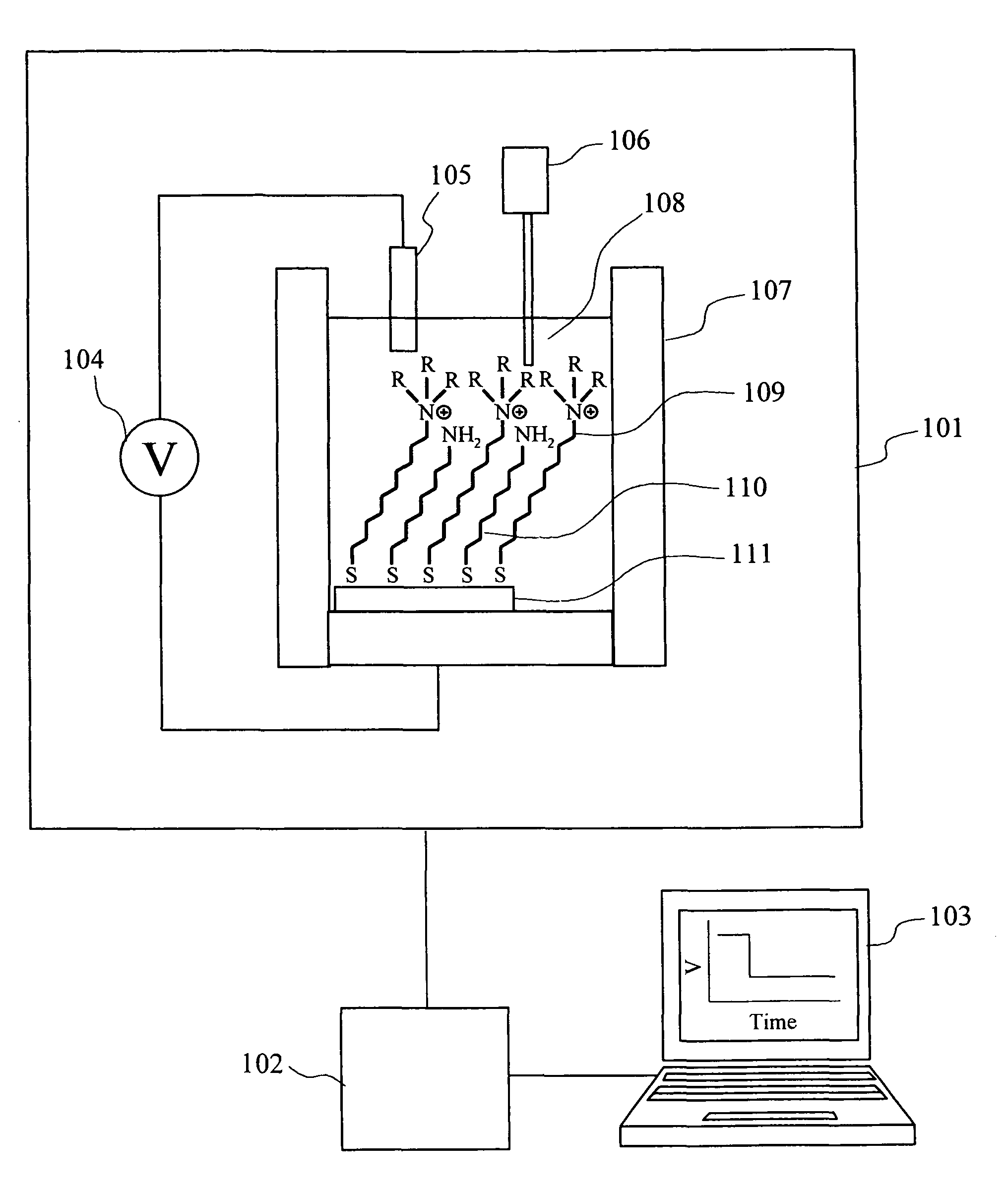
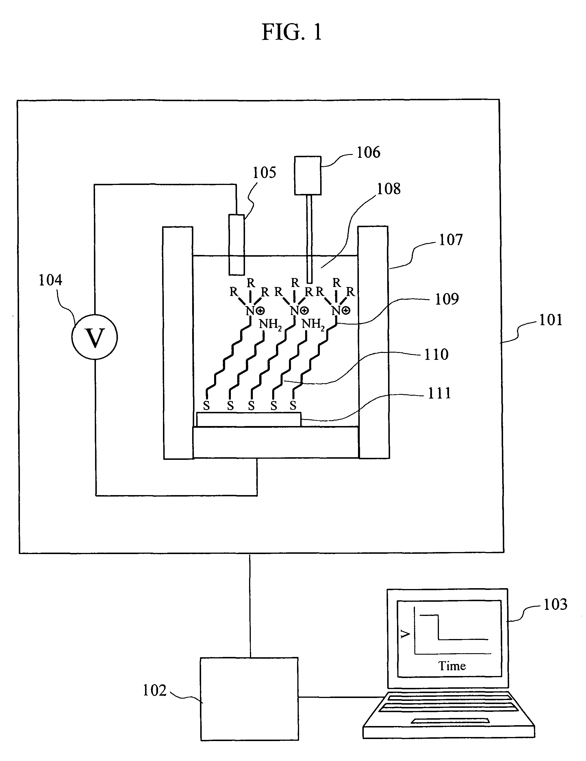
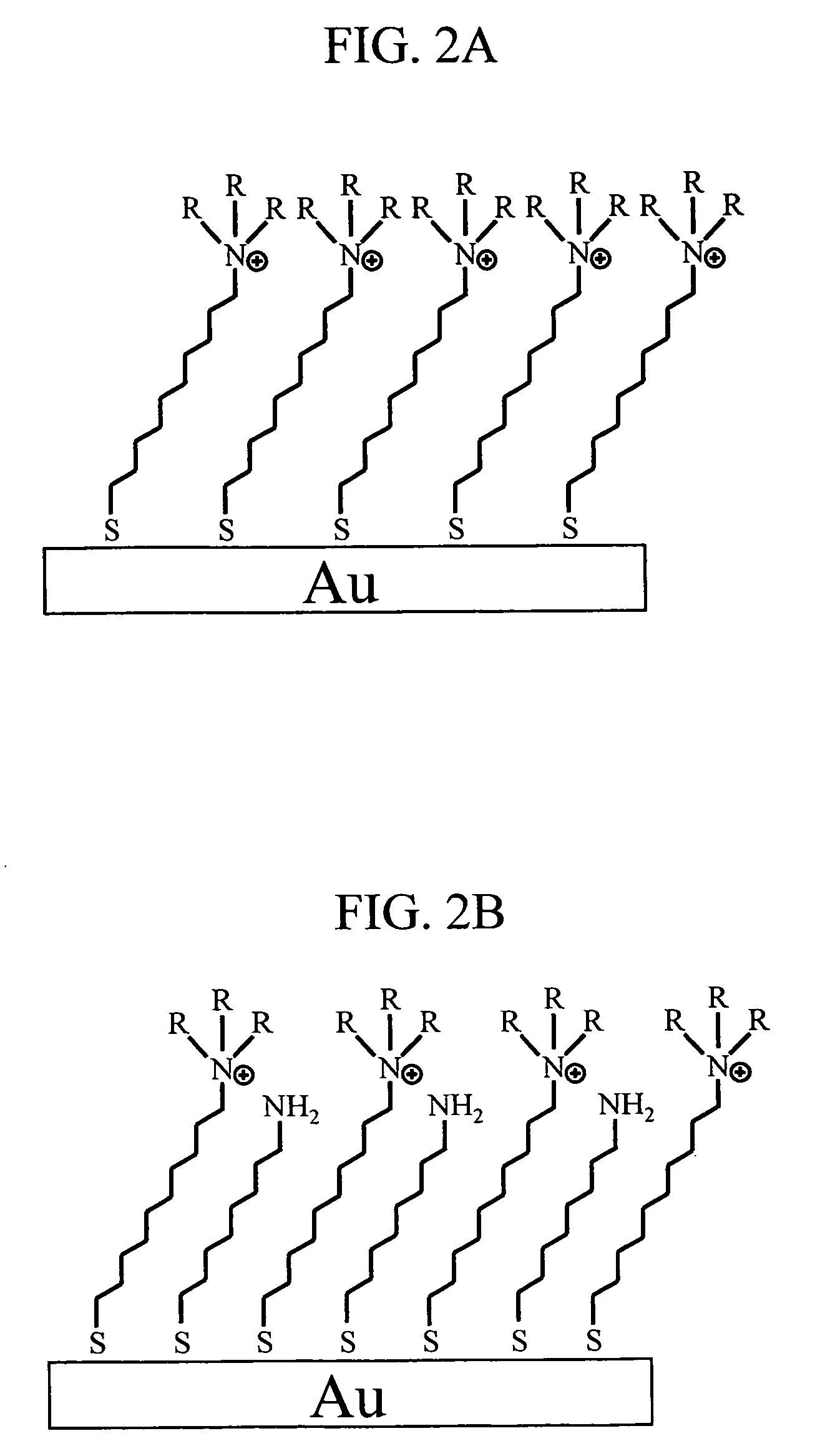
[0024]FIG. 1 is a block diagram indicating one example of an ion concentration measuring device according to the present invention. The measuring device in this embodiment includes a measurement section 101, a signal processing circuit 102, and a data processor 103. The measurement part 101 includes a potentiometer 104, a reference electrode 105, a sample solution injector 106 that supplies a sample solution having an analyte, and a measurement cell 107. The reference electrode 105A and a gold electrode 111 to which a quaternary ammonium salt derivative 109 serving as a ligand for an anion and an alkanethiol 110 having an amino group at its terminal are immobilized, are arranged in a measurement solution 108 in the measurement cell 107. FIG. 2 shows one example of an immobilization method of a ligand to a gold electrode. FIG. 2A shows a case where only a ligand is immobilized; an...


PUM

PropertyMeasurementUnit
sizeaaaaaaaaaa
thicknessaaaaaaaaaa
electrode potentialaaaaaaaaaa

Abstract

The present invention aims to simplify the structure and a fabrication method of an ion-selective electrode in an ion concentration measuring device that measures an anion, particularly a chloride ion, in a biological component. To this end, in a potential difference measuring unit, a quaternary ammonium salt derivative serving as a ligand for an anion is immobilized to the surface of a gold electrode by using as a linker an insulative molecule forming a self-assembled monolayer. The potential difference measuring unit measures an electromotive force generated with anion binding, as an interface potential change on the surface of the gold electrode. In order to reduce the influence of adsorption of impurities on the electrode surface, a high-molecular weight polymer is physically adsorbed on the gold electrode and thus used when a biological component is measured.

Description

CLAIM OF PRIORITY[0001]The present application claims priority from Japanese patent applications JP 2007-242790 filed on Sep. 19, 2007 and JP 2008-149385 filed on Jun. 6, 2008, the contents of which are hereby incorporated by reference into this application.BACKGROUND OF THE INVENTION[0002]1. Field of the Invention[0003]The present invention relates to an anion concentration measuring device to measure anions, particularly chloride ions, in a biological component.[0004]2. Description of the Related Art[0005]Ion-selective electrode techniques are widely used as methods of analyzing the concentrations of biological substances in the medical field, particularly, electrolytes (sodium ions, potassium ions, and chloride ions, and the like) in serums and plasmas. In the ion-selective electrode techniques, the ion concentration in a sample can be measured by simply immersing an ion-selective electrode together with a reference electrode in the sample solution. Thus, the ion-selective electr...

Claims


Application Information

Patent Timeline
Patent Type & Authority Patents(United States)
IPC IPC(8): G01N27/333
CPCG01N27/3335G01N27/414
Inventor KAMAHORI, MASAOISHIGE, YUYAMASHITA, KOTAROSHIBATA, YASUHISAMIYAKE, MASAFUMINAGAMINE, KUNIAKI
Owner HITACHI HIGH-TECH CORP
Learn More