
Filter medium

a filter medium and filter medium technology, applied in the field of filter medium, can solve the problems of correspondingly high burst pressure, limited filtration performance, and failure of membrane material surrounded in this way, and achieve the effect of high filtration performan

Inactive Publication Date: 2013-03-12
POROMEDIA
View PDF10 Cites 2 Cited by
  • Summary
  • Abstract
  • Description
  • Claims
  • Application Information

AI Technical Summary

Benefits of technology

This patent is about an improved filter medium that offers better filtration performance and durability. The filter medium includes at least one other filter membrane with another fabric ply as a support and protective layer. Between the two membranes, a third fabric ply extends, and both sides of the membrane are applied non-positively to a simultaneously supporting and draining central fabric as the third fabric ply. This double-sided filter structure ensures high filtration performance and strong lamination for long usage. The driving force for filtration can be obtained through reversed flushing processes or a combination of negative pressure and overpressure. The fabric plies are held together with additional binding threads, and there are open passage sites for fluid flow. The flat filter material reduces shifting of threads and accommodates high internal pressure.

Problems solved by technology

Due to the indicated diagonal reinforcement, it has a correspondingly high burst pressure; but the performance in filtration is limited.
In spite of support by the liquid-permeable diagonal reinforcement, in severe filtration operation the membrane material surrounded in this way can fail.
The known fabrics in the form of a basket weave or a cross weave are regarded as disadvantageous because they lack dimensional stability and have a low modulus and low strength in the oblique direction of the fabric laminate.
The disadvantage in this known solution is that the indicated multiaxial fabric is relatively complex and expensive to produce, making the membrane material more expensive.
Furthermore, this solution is limited in filtration performance by its basic structure of the membrane material.
Especially when the filter cake is removed or discarded, the filter medium is exposed to considerable mechanical loads which can be managed with the known filter medium.
Still, the filtration performance is not satisfactory even in this durable solution.

Method used


Image

  • Filter medium
  • Filter medium

Examples


Embodiment Construction

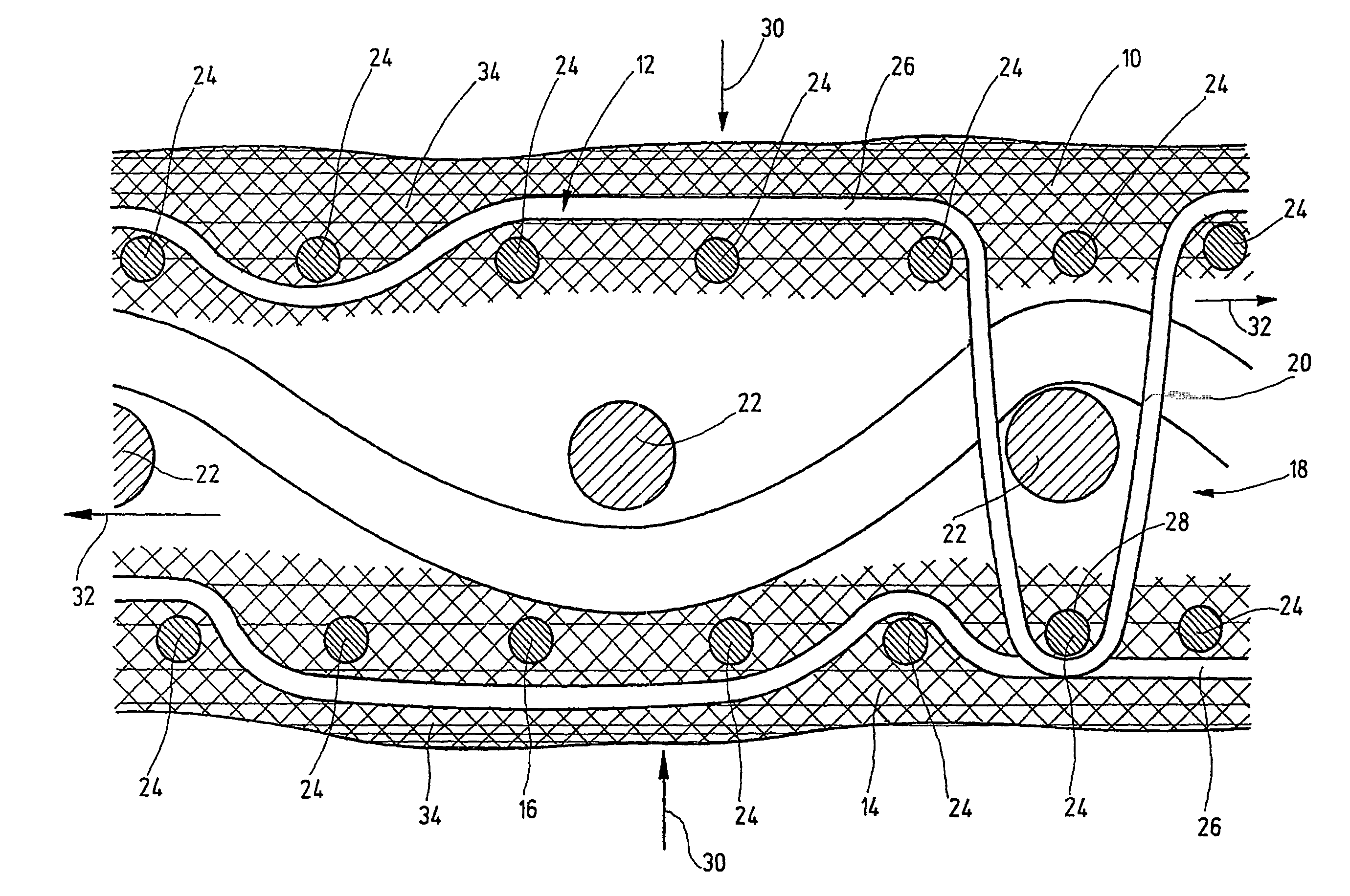
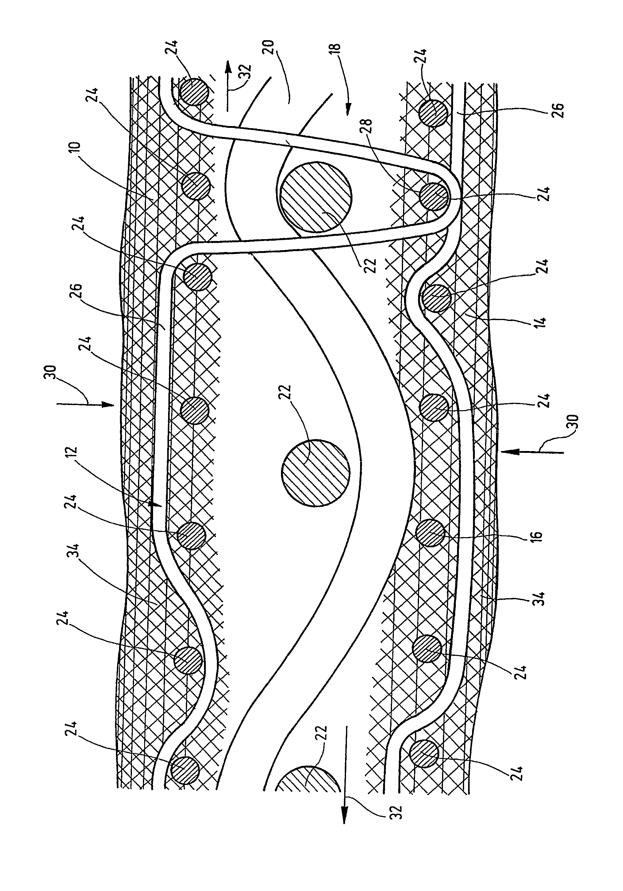
[0019]The filter medium, according to an exemplary embodiment of the present invention, has an upper filter membrane 10 with a fabric ply 12 as the support and protective layer. The filter medium has another lower filter membrane 14 with another fabric ply 16 as the support and protective layer. A third fabric ply 18 extends between the two adjacent filter membranes 10, 14. This third fabric ply 18 has a thread system of warp threads 20 and weft threads 22. The warp threads 20 form the longitudinal fiber system, and the weft threads form the transverse thread system of the third fabric ply 18. These longitudinal and transverse threads can be interchanged such that the warp threads 20 form the weft thread system and the weft threads 22 form the warp thread system. The upper fabric ply 12 and the lower fabric ply 16 are likewise composed of a longitudinal and a transverse thread system with individual warp threads (not shown) and weft threads 24. As the FIGURE shows, by threads 26 mad...


PUM

PropertyMeasurementUnit
Timeaaaaaaaaaa
Diameteraaaaaaaaaa

Abstract

A filter medium includes at least one filter membrane (10) having a fabric ply (12) as a supporting and protective layer. At least one additional filter membrane (14) with another fabric ply (16) as a supporting and protective layer is also provided. A third fabric ply (18) extends between both adjacent filter membranes (10, 14). Both adjacent filter membranes (10, 14) are connected together by the threads (26) of the other two plies (12, 16) which reach through to the third ply (18).

Description

FIELD OF THE INVENTION[0001]The present invention relates to a filter medium with at least one filter membrane having a fabric ply as the support and protective layer.BACKGROUND OF THE INVENTION[0002]EP 0 761 292 A1 discloses self-supporting capillary membranes for use at higher pressure with an internal separating layer. This known capillary membrane is provided with a seamless outside jacket made as a closed, liquid-permeable diagonal reinforcement. The diagonal reinforcement has individual threads including for their part either of monofilaments or multifilaments. The material selection for these monofilaments or multifilaments is almost unlimited. For example, polyester yarns, polyaramides, polymer fibers, glass fibers, or metal filaments are used. The individual threads of the diagonal reinforcement are applied to the capillaries in a 1:1 to 2:1 or even 2:2 braid binding in a continuous process as a seamless outer jacket. Depending on the wall thickness of the monofilaments or ...

Claims


Application Information

Patent Timeline
IPC IPC(8): B01D69/10B01D69/00B01D69/08B01D69/12
CPCB01D69/08B01D69/10B01D69/12B01D69/1071B01D69/1213
Inventor KAMLEITER, MICHAELGUDERNATSCH, WILHELM N.
Owner POROMEDIA
Learn More