
Angle sensor, system and method employing guided-mode resonance

a guided-mode resonance and sensor technology, applied in the field of sensors, can solve the problems of deterioration and calibration drift of simple normal angle detectors based on corner reflectors, prohibitively expensive manufacture and deployment of mems devices,

Inactive Publication Date: 2013-03-05
HEWLETT-PACKARD ENTERPRISE DEV LP
View PDF13 Cites 4 Cited by
  • Summary
  • Abstract
  • Description
  • Claims
  • Application Information

AI Technical Summary

Benefits of technology

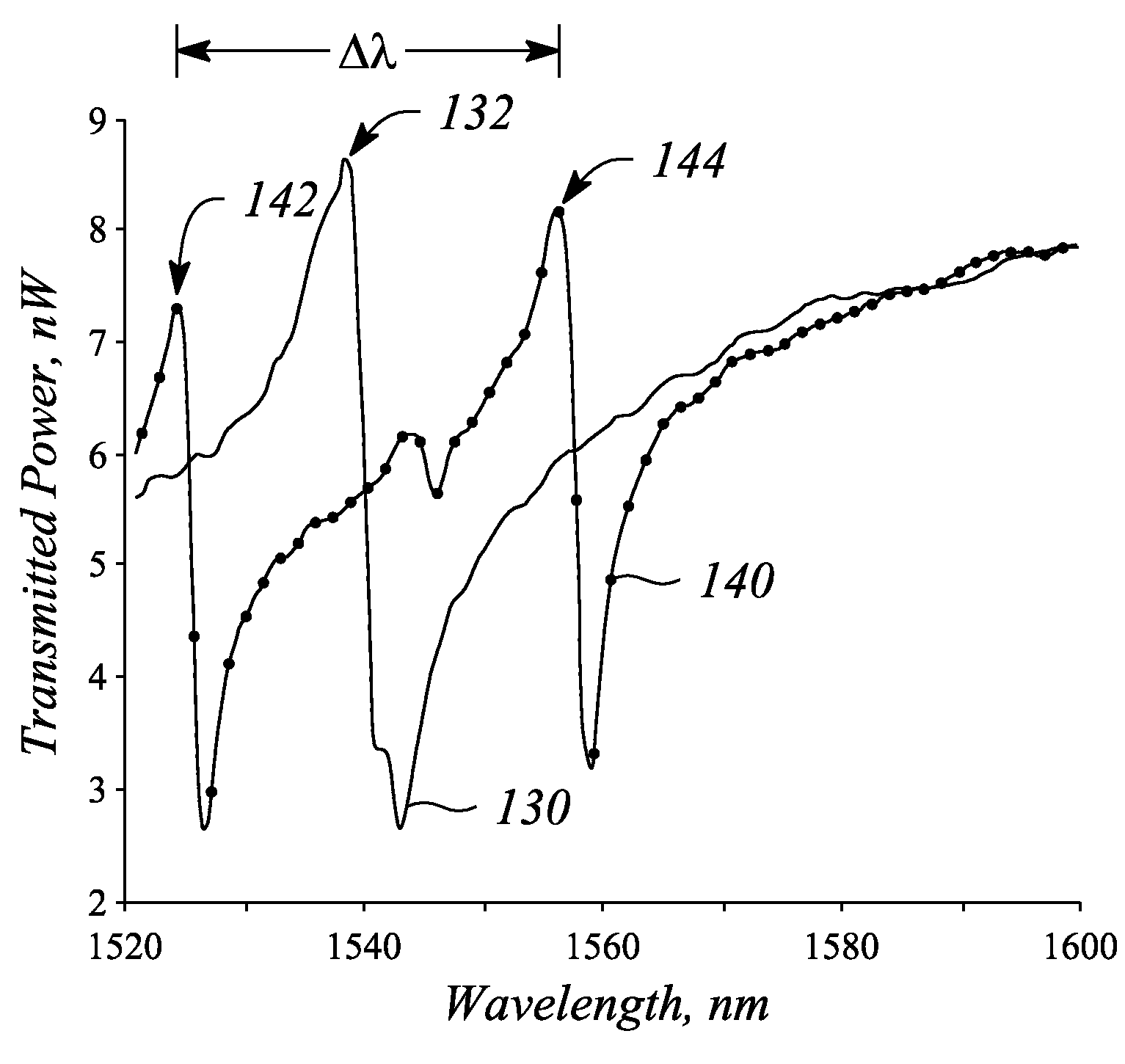
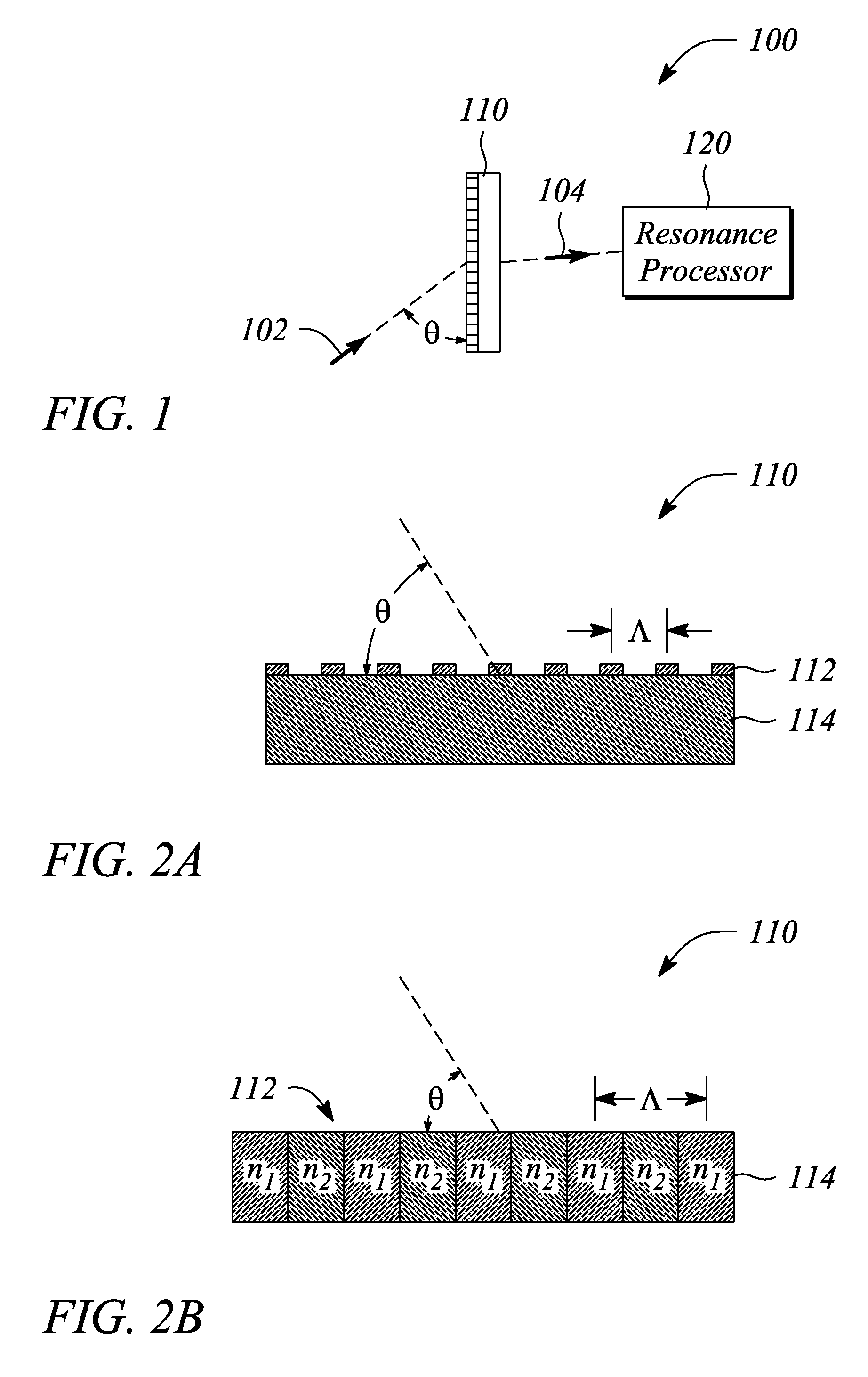
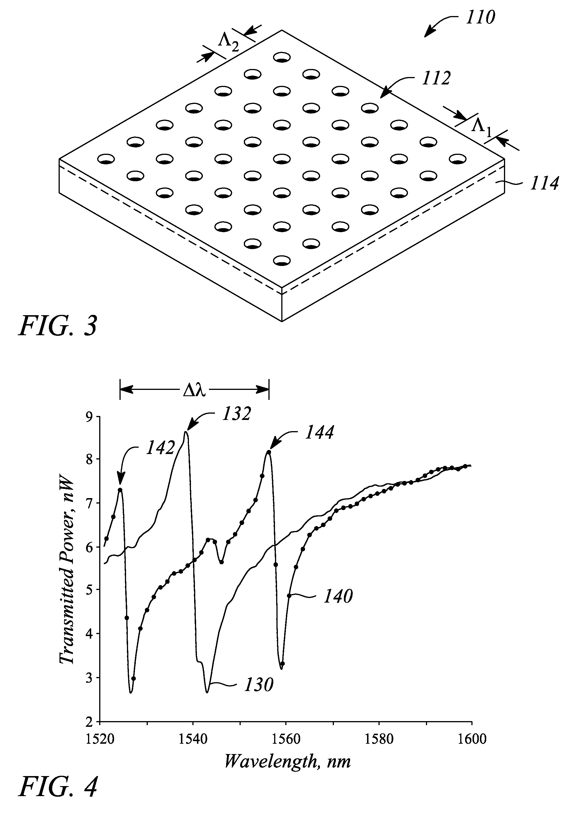
The present invention provides an angle sensor using guided-mode resonance (GMR) gratings and a resonance processor to determine the angle of incidence of a signal incident on the GMR grating. The angle sensor has improved accuracy in determining the angle of incidence compared to previous methods. The angle sensing system also includes an optical source and a GMR grating for detecting the guided-mode resonance and determining the angle of incidence of the incident signal. The method of incident angle determination involves detecting guided-mode resonances in the GMR grating and determining the angle of incidence from the spacing between the guided-mode resonances or the spectral distance between them. The angle sensor can be used in various applications such as optical navigation and object detection.

Problems solved by technology

Unfortunately, MEMs devices often can be prohibitively expensive to manufacture and deploy.
Laser interferometery and collimated optical source-based angle sensing is similarly expensive and typically require stable (often extremely stable) operating conditions for accurate angle determination.
Even very simple normal angle of incidence detectors based on corner reflectors can suffer from degradation and calibration drift over time due, in part, to changes in a surface condition of the reflectors due to environmental factors.
Moreover, these technologies often present a problem during integration into an integrated circuit (IC) or during manufacturing when conventional fabrication technologies is desired.

Method used


Image

  • Angle sensor, system and method employing guided-mode resonance
  • Angle sensor, system and method employing guided-mode resonance
  • Angle sensor, system and method employing guided-mode resonance

Examples


Embodiment Construction

[0021]Embodiments of the present invention facilitate one or both of determining an angle of incidence of a signal and determining an angular orientation of a planar surface relative to the incident signal. In particular, the planar surface is a surface of a guided-mode resonance (GMR) grating. A guided-mode resonance induced in the GMR grating by the signal is employed to determine the angle of incidence. The GMR-based angle determination embodiments of the present invention generally exhibit high sensitivity, high angular resolution and a large dynamic range. Moreover, the GMR-based angle determination embodiments are relatively unaffected by fluctuations in an intensity of the signal and one or both of may be relatively resilient to certain physical degradation of the planar surface and is capable of relatively high refresh rates (>1 MHz), for example. As such, GMR-based angle determination may be employed in a wide variety of operational environments and conditions as well as ma...


PUM


Abstract

An angle sensor, system and method employ a guided-mode resonance. The angle sensor includes a guided-mode resonance (GMR) grating and a resonance processor. The resonance processor determines an angle of incidence of a signal incident on the GMR grating. The resonance processor uses a guided-mode resonance response of the GMR grating to the signal to determine the angle of incidence. The angle sensing system includes the GMR grating, the resonance processor and further includes an optical source that produces the signal. The method includes providing a GMR grating, detecting a guided-mode resonance produced in the GMR grating when subjected to an incident signal, and determining an angle of incidence of the incident signal from one or both of a number of and a spectral distance between guided-mode resonances present in a response of the GMR grating to the incident signal.

Description

CROSS-REFERENCE TO RELATED APPLICATIONS[0001]N / ASTATEMENT REGARDING FEDERALLY SPONSORED RESEARCH OR DEVELOPMENT[0002]N / ABACKGROUND[0003]1. Technical Field[0004]The invention relates to sensors. In particular, the invention relates to devices employed as angle sensors.[0005]2. Description of Related Art[0006]Angle sensors are employed in a wide variety of applications to determine and monitor angular orientation and motion. For example, angle sensors are commonly employed in control systems to monitor and control an orientation and / or motion of a particular element of the system. Applications that employ angle sensors range from spacecraft and satellite attitude / orientation control to orienting a substrate during manufacturing. As such, angle sensors and angle sensing are commonly found in devices and systems such as consumer electronics, automobiles, manufacturing equipment, navigation systems, and even communication systems (e.g., antenna position control).[0007]In general, angle s...

Claims


Application Information

Patent Timeline
Patent Type & Authority Patents(United States)
IPC IPC(8): G01B11/26G01C1/00G01J3/28
CPCG01B11/26G01D5/38
Inventor FATTAL, DAVID A.PYAYT, ANNABEAUSOLEIL, RAYMOND G.WU, WEI
Owner HEWLETT-PACKARD ENTERPRISE DEV LP
Learn More