
Method for determining directionality using bluetooth low energy communications

a low-energy communication and directionality technology, applied in the field of communication methods and systems, can solve problems such as obvious disadvantages of conventional approaches

Active Publication Date: 2016-04-14
AVAGO TECH INT SALES PTE LTD
View PDF3 Cites 73 Cited by
  • Summary
  • Abstract
  • Description
  • Claims
  • Application Information

AI Technical Summary

Benefits of technology

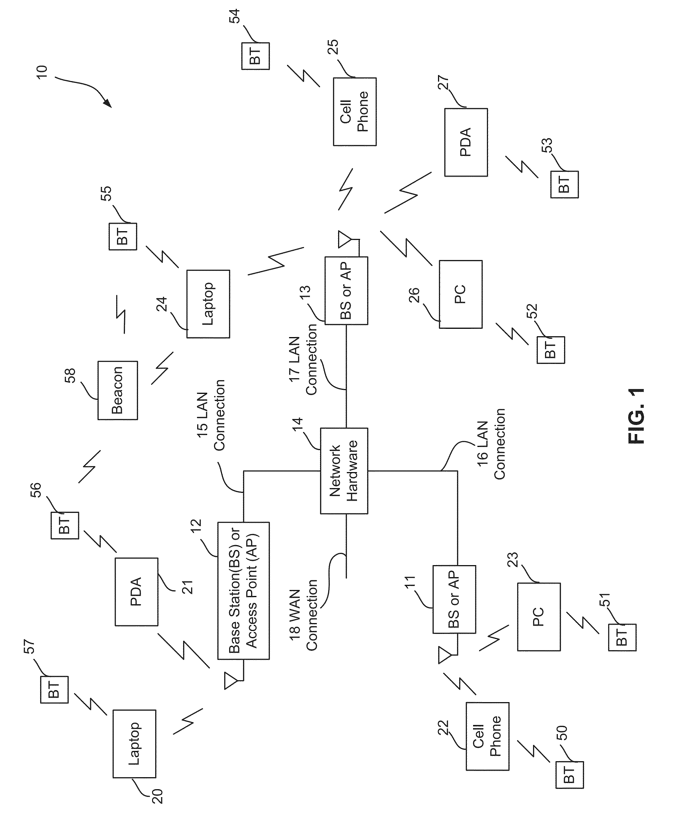
The present patent is about a method and system for communications using Bluetooth low energy (BLE) technology. The technical effects of this patent include providing updated information for determining the relative angle of one device to another object (e.g., beacon or other device) by broadcasting the directionality field in a power efficient manner across the BLE data channels. The patent also describes a wireless communication system that includes a plurality of base stations and access points, and a plurality of wireless communication devices. The wireless communication devices may be laptop computers, personal digital assistants, personal computers, cellular telephones, or any other type of device that supports wireless communications.

Problems solved by technology

Disadvantages of conventional approaches will be evident to one skilled in the art when presented in the disclosure that follows.

Method used


Image

  • Method for determining directionality using bluetooth low energy communications
  • Method for determining directionality using bluetooth low energy communications
  • Method for determining directionality using bluetooth low energy communications

Examples


embodiment 200

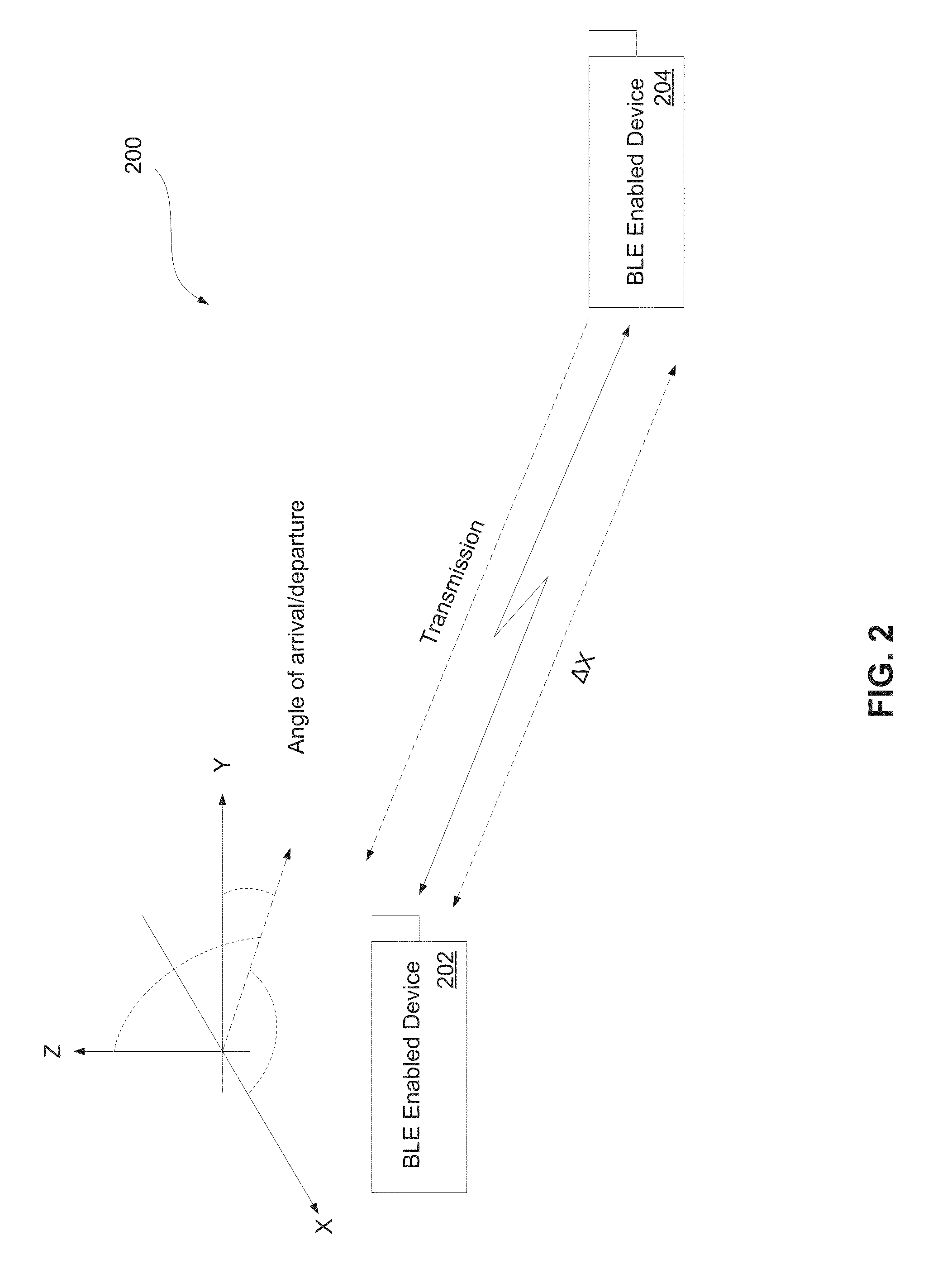
[0028]FIG. 2 is a block diagram showing an embodiment of a directional relationship between two Bluetooth wireless communication devices in accordance with the present disclosure. As shown, embodiment 200 illustrates a physical relationship between at least a first wireless communication device 202 (BLE enabled) and a second communication device (wireless or wired) 204 (also BLE enabled) in terms of angle of arrival / departure estimation there between. The two communication devices 202 and 204, separated by some distance X. As a communication is transmitted from second communication device 204 to first wireless communication device 202, the communication or received signal will arrive at first wireless communication device 202 at a particular angle (as defined with respect to some reference of the first wireless communication device 202). Angle of incidence circuitry (e.g., a processor in association with computer code) resident on the first wireless communication device 202 will det...

first embodiment

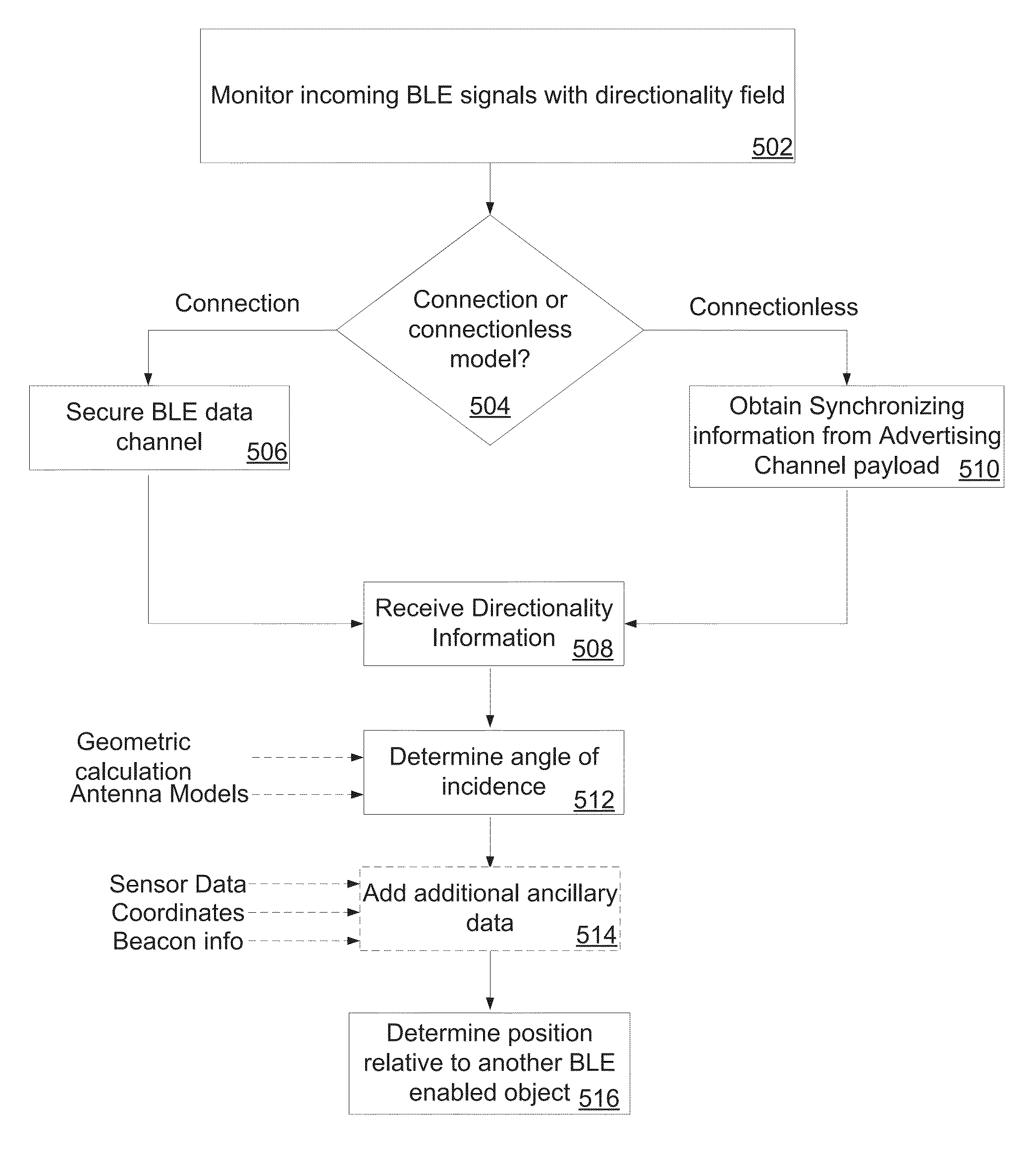
[0048]In a first embodiment, frequency diversity is added to AoD with a method for broadcast synchronization on the 37 BLE data channels. In this embodiment, samples are collected across multiple frequencies with a majority vote. Since the embodiments disclosed herein for BLE AoA / AoD transmit an all ones, un-whitened field at the end of a normal BLE packet, a tracking device only needs to receive the all ones field and determines phase difference relative to the physical geometry of an antenna array which exists at least on one side but may exist on both. In one embodiment, frequency hopping occurs on all 37 channels which are then combined together to determine actual angle of incidence.

[0049]FIG. 7 is a diagram illustrating an example embodiment 700 of detecting angle of arrival and angle of departure for a target in accordance with the present disclosure. As shown, antenna arrays 706 and 708 are present on both the target 702 and tracker 704 (each side's antennas shown separately...


PUM


Abstract

A method and system detect directionality between two objects by measuring angles of signals incident on antenna arrays on at least one side to determine angle of incidence. The methods utilize Bluetooth Low Energy communications as the means for both the control protocol and for providing updated information for deriving directionality. Directionality information is broadcast on selected BLE advertising or data channels, or broadcast using a hopping pattern over the BLE data channels, both at a specific interval duty cycle. If a hopping pattern is selected to transmit directionality information, then anchor information is simultaneously broadcast on the BLE advertising or data channels at a different, asynchronous duty cycle. In additional embodiments, signals incident on antenna arrays located on both target and tracking sides are used to determine angle of incidence, separate antennas are combined to form new antennas and antenna models are used to anticipate known antenna structure responses.

Description

CROSS REFERENCE TO RELATED PATENTS[0001]The present U.S. Utility Patent Application claims priority pursuant to 35 U.S.C. §119(e) to U.S. Provisional Application No. 62 / 063,827, entitled “Method for Determining Angle of Arrival Using Bluetooth Low Energy”, filed Oct. 14, 2014, which is hereby incorporated herein by reference in its entirety and made part of the present U.S. Utility Patent Application for all purposes.STATEMENT REGARDING FEDERALLY SPONSORED RESEARCH OR DEVELOPMENT[0002]Not ApplicableINCORPORATION-BY-REFERENCE OF MATERIAL SUBMITTED ON A COMPACT DISC[0003]Not ApplicableBACKGROUND[0004]1. Technical Field[0005]The present disclosure relates to a method and system for communications. More specifically, it is related to Bluetooth® applications.[0006]2. Description of Related Art[0007]Bluetooth® (hereinafter “BT”) wireless technology is a short-range communications system utilized to wirelessly link portable and / or fixed electronic devices, such that cables and wires that w...

Claims


Application Information

Patent Timeline
IPC IPC(8): H04W4/00H04W48/12H04W56/00H04W4/80
CPCH04W4/008H04W84/18H04W48/12H04W56/001H04W64/006G01S3/046G01S3/46G01S5/0247H04W4/80G01S5/02216G01S1/00
Inventor POLO, ANGEL ARTUROBAKER, THOMAS FRANCISHERNDON, MICHAEL DAVIDJIN, ARTHUR HCHEN, FREDRICK LEE
Owner AVAGO TECH INT SALES PTE LTD
Learn More