Generator with output options and low loss windings

a technology of windings and generators, applied in the direction of windings, synchronous generators with multiple outputs, electric generator control, etc., can solve the problems of wattage loss in heating diodes and heat sinks, inability to use y type windings, and large loss

Inactive Publication Date: 2013-02-19
GERFAST STEN R
View PDF15 Cites 0 Cited by
  • Summary
  • Abstract
  • Description
  • Claims
  • Application Information

AI Technical Summary

Benefits of technology

[0016]A further object of the present invention is to be able to use either “claw type” rotors with carbon-brush-slip-ring system used on many alternators sold today, or use a permanent magnet rotor that would make the generator described in the present invention totally carbon-brush-free by replacing each “claw” part with a permanent magnet pole. The P.M. rotor eliminates all slip ring components and makes the generator more reliable, simpler, smaller and less costly.
[0017]Yet another object is to decrease the size and cost of the switching components, such as relays, semi conductors and switches.
[0022]The present invention has a split output with a large portion being AC output, and therefore the switching using Triac's and S.C.R.'s is accomplished with less cost and greater reliability. Electric motors that are used in the automotive field today are DC motors with carbon brushes that have a finite life before the brushes (or the whole motor) has to be replaced.
[0023]With a supply of AC power available, AC induction motors could be used in place of some of these motors. AC motors do not require any carbon brushes and is therefore more reliable.
[0025]Incandescent lamps operates equally well on both AC and DC and could be switched into the above described first output that is AC power. Window heating can be used with AC as well. Lamps such as head lamps, brake lights, back-up lamps and all the other lamps that is on an automobile, bus or truck today can easily draw 40 amperes from an 80-ampere alternator. This lamp load, if powered solely by AC power and switched by AC rated “switches”, could decrease losses and therefore increase fuel efficiency.
[0039]All the above mentioned savings of generator / alternator power, the increase in fuel efficiency, at a lower cost with greater reliability, is one of the basis of the present invention.

Problems solved by technology

But that is not possible with Y type windings.
This wattage is lost in heating the diode and its heat sink.
In an alternator with its heavy current this loss can be substantial.
And of course that power, and power loss, comes from gasoline burned in the engine.
Which means decreased fuel economy.

Method used


Image

  • Generator with output options and low loss windings
  • Generator with output options and low loss windings
  • Generator with output options and low loss windings

Examples


Embodiment Construction

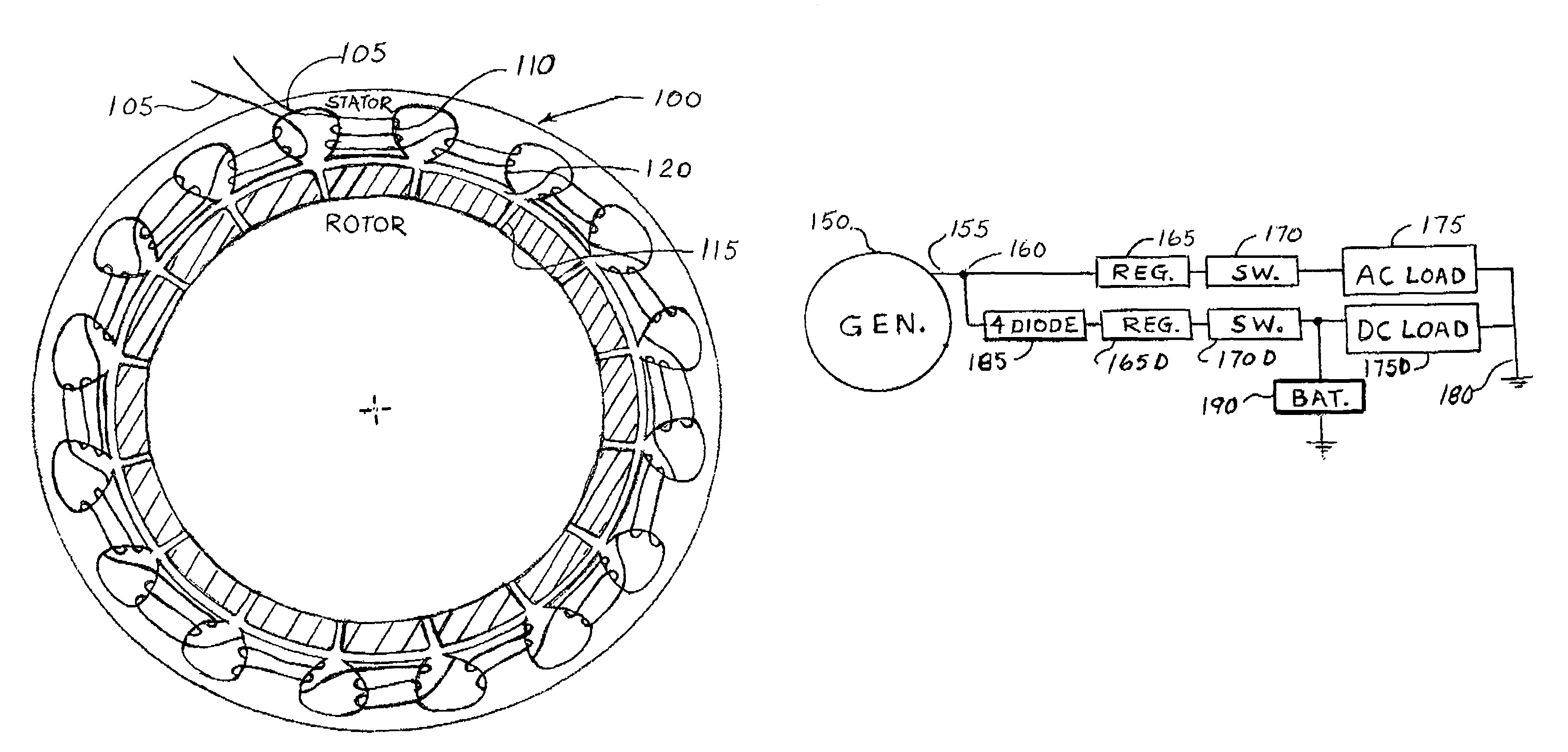
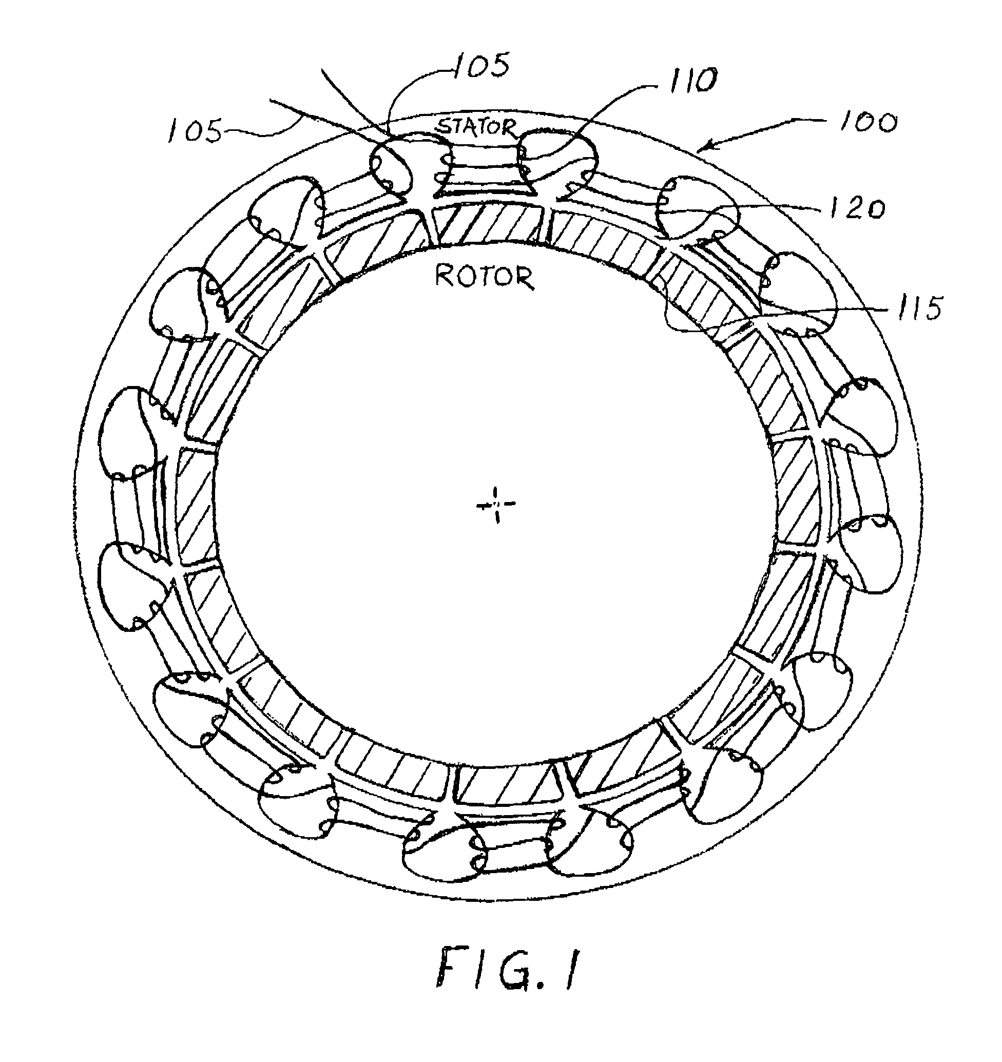
[0046]FIG. 1 is a view of the wound stator 100 of the present invention showing the alternately wound magnet wire windings 105 on salient stator poles 110 that are made from lamination steel. The windings 105 are shown series connected having two free ends. The rotor poles 115 that are of the same width as the salient stator poles 110 and are made from permanent magnet material. Also shown is a small air gap 120 between the rotor face and the stator face.

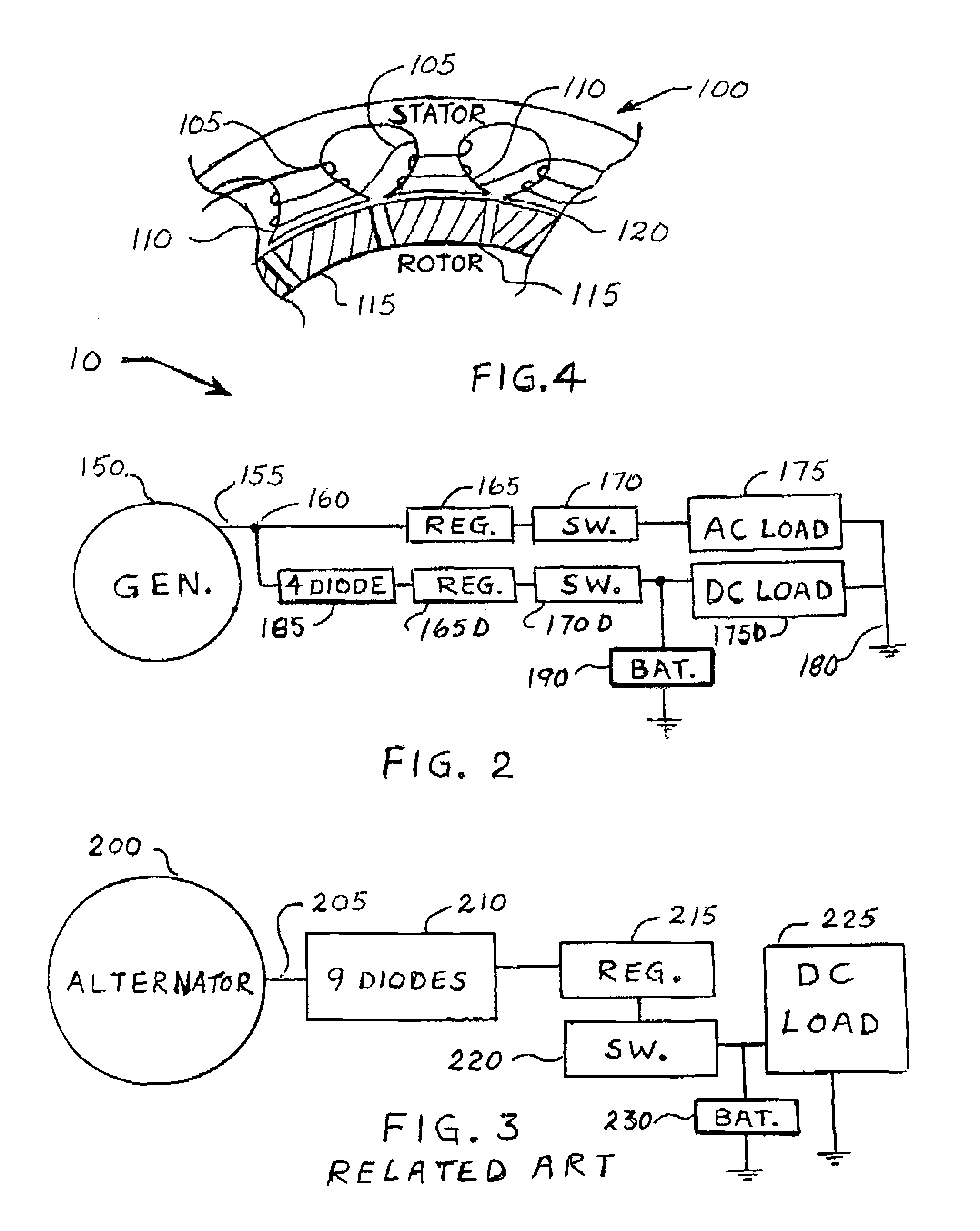
[0047]FIG. 2 is showing a block diagram of the generator system 10 of the present invention. It has a generator 150 with a first AC output 155 split into AC and DC at point 160, an AC voltage regulator 165 that is connected to AC rated switches 170. These switches can be manual switches, relays, semi-conductor switches or computer controlled switch functions, and are connected to AC loads 175. Both AC and DC loads have common ground point 180. The split point 160 is also connected to 4 diodes in a bridge type circuit 185 with the DC...


PUM


Abstract

A more fuel efficient automotive generator, then present alternators, because of its better magnetic utilization of its series connected copper windings on its salient stator poles. It also has output options for resistive loads as well as for direct current devises with both options designed for lower cost, smaller physical size, greater electrical efficiency and lower diode losses.

Description

TECHNICAL FIELD[0001]This invention relates to automotive generators and its windings and to the switching and usage of its electrical power generated. Switches, semi-conductors or relays are used to connect that power to lamps, actuators, window heating and electrical motors that are used in cars, busses and trucks. It also relates to a split output winding that has output options that include both AC and DC. and to how that output switching is accomplished.DESCRIPTION OF RELATED ART[0002]Automotive vehicles today use an alternator / generator to supply current to the lamps, relays, actuators, window heating and electrical motors that are on the vehicle. In addition the alternator / generator also have to keep the vehicles battery charged. Over the year cars have had evolutionary steps in design to get better performance and better fuel efficiency.[0003]Cars in the past had 6-volt systems that was changed to 12-volt systems, with proposals to go to a 36 / 42 volt design in the near futur...

Claims


Application Information

Patent Timeline
Patent Type & Authority Patents(United States)
IPC IPC(8): H02K3/00H02K1/00H02K19/22H02K19/34H02K19/36H02K21/16H02K21/48H02K23/64H02P9/30
CPCH02K19/22H02P9/307H02K21/16H02K19/34H02K19/36H02P2101/45H02K21/48
Inventor GERFAST, STEN R.
Owner GERFAST STEN R
Why Eureka
Try Eureka