
Induction heating device

a technology of induction heating and temperature measurement, which is applied in the direction of induction heating, electric/magnetic/electromagnetic heating, electrical equipment, etc., can solve the problem of decreasing the accuracy of temperature measurement by temperature detector, and achieve the effect of high accuracy

Inactive Publication Date: 2013-02-19
PANASONIC CORP
View PDF24 Cites 3 Cited by
  • Summary
  • Abstract
  • Description
  • Claims
  • Application Information

AI Technical Summary

Benefits of technology

[0007]The present invention is an induction heating device which is made user-friendly by illuminating the area over a thermo-sensitive device through the top plate so as to show the correct position of the thermo-sensitive device on the top plate, and which has an infrared sensor detecting temperature with high accuracy.
[0008]The induction heating device of the present invention includes a top plate, a thermo-sensitive device, a temperature detector, a coil, a controller, and a light-emitting section. The top plate places thereon a cooking utensil containing material to be cooked. The thermo-sensitive device changes its electrical characteristics with the temperature of the cooking utensil. The temperature detector detects the temperature of the cooking utensil based on the electrical characteristics of the thermo-sensitive device. The coil heats the cooking utensil. The controller controls the coil based on the temperature information of the temperature detector, thereby controlling an amount of the electric heating power to be supplied to the cooking utensil. The light-emitting section emits visible light to the area over the thermo-sensitive device. The light from the light-emitting section illuminates the area over the thermo-sensitive device through the top plate. With this structure, the light-emitting section shows the correct position of the thermo-sensitive device on the top plate so as to make the heating device user-friendly, and the thermo-sensitive device detects temperature with high accuracy.

Problems solved by technology

This, however, causes infrared sensor 23 to receive the infrared radiation from not only cooking utensil 21 but also other sources, decreasing the accuracy of the temperature measured by temperature detector 24.

Method used


Image

  • Induction heating device
  • Induction heating device
  • Induction heating device

Examples


Embodiment Construction

[0013]An embodiment of the present invention will be described as follows with reference to drawings. Note that the present invention is not limited to this embodiment.

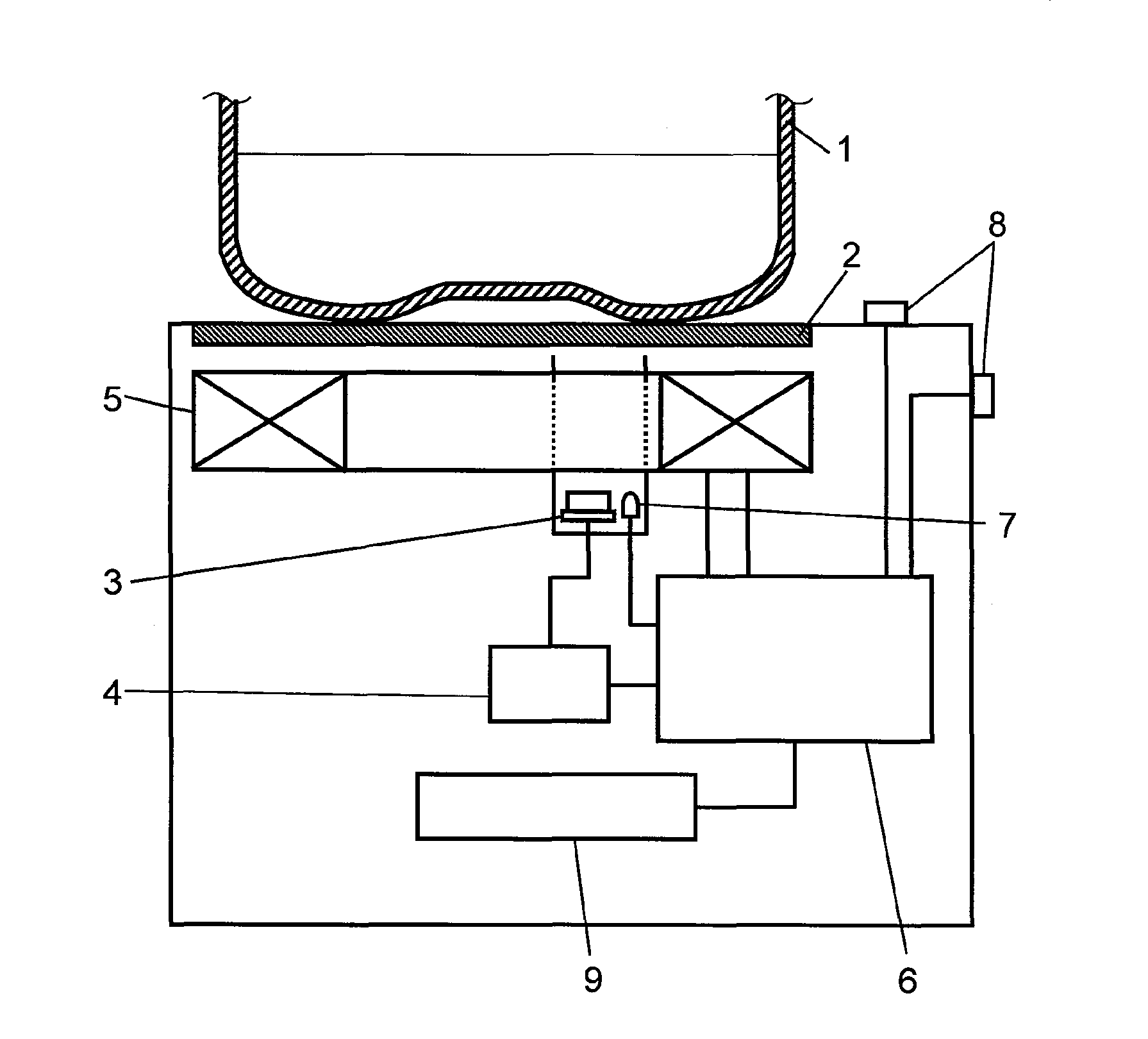
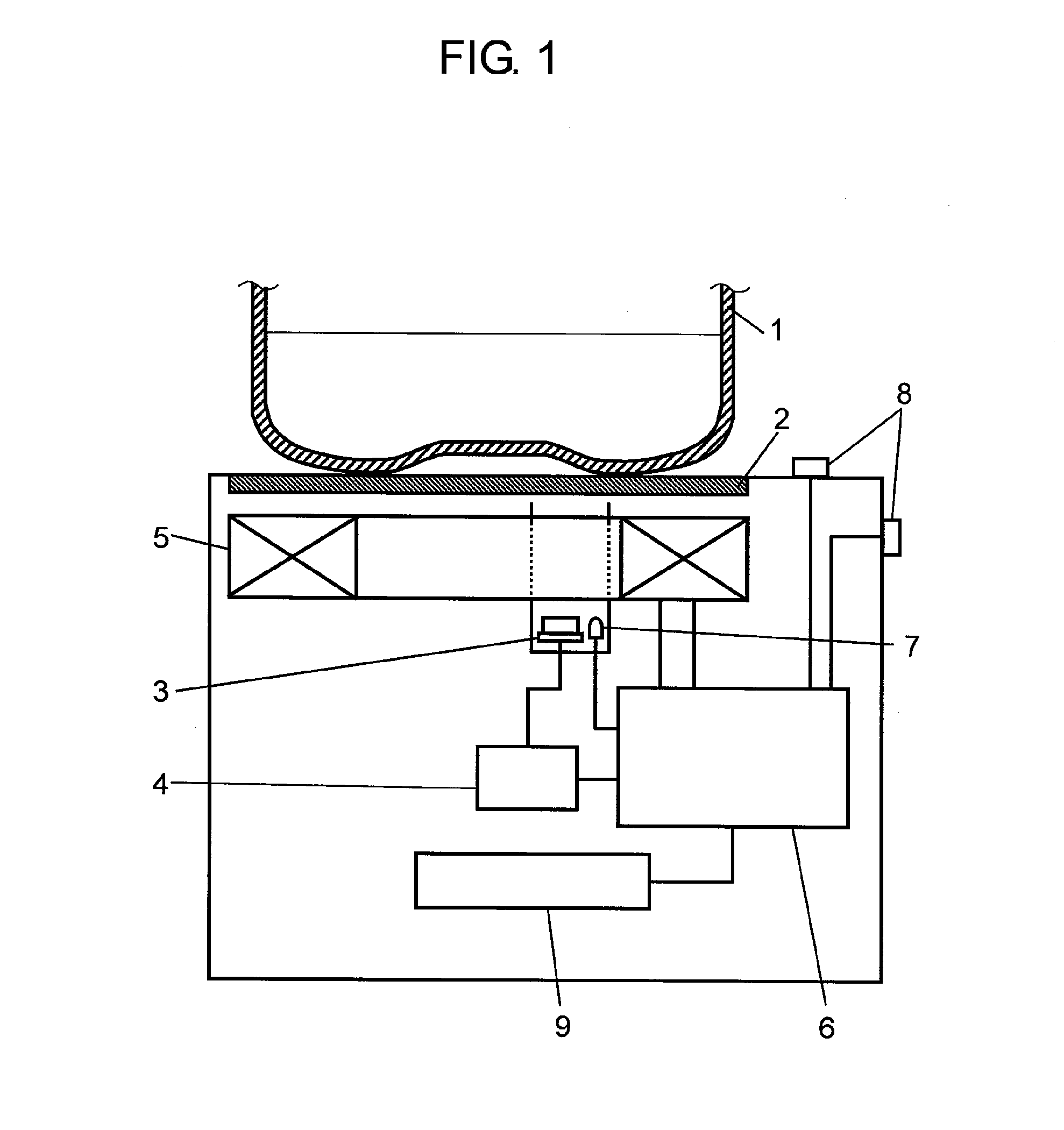
[0014]FIG. 1 is a schematic configuration view of an induction heating device according to an embodiment of the present invention. The heating device includes top plate 2, infrared sensor 3, temperature detector 4, heating coil 5, controller 6, light-emitting section 7, and input sections 8.

[0015]Top plate 2 is a part of the outer shell of the device. On top plate 2, cooking utensil 1 is placed. Cooking utensil 1 contains material to be cooked. Top plate 2 is made, for example, of heat resistant tempered glass and formed flat, thus providing easy cleaning and fine appearance. At least the portion of top plate 2 that is just above infrared sensor 3 is light-transmissive.

[0016]Infrared sensor 3, which is a thermo-sensitive device for detecting the temperature of cooking utensil 1, receives and detects the infrared radia...


PUM


Abstract

An induction heating device includes a top plate, a thermo-sensitive device, a temperature detector, a coil, a controller, and a light-emitting section. The top plate places thereon a cooking utensil containing material to be cooked. The thermo-sensitive device changes its electrical characteristics with the temperature of the cooking utensil. The temperature detector detects the temperature of the cooking utensil based on the electrical characteristics of the thermo-sensitive device. The coil heats the cooking utensil. The controller controls the coil based on the temperature information of the temperature detector, thereby controlling an amount of the electric heating power to be supplied to the cooking utensil. The light-emitting section emits visible light to the area over the thermo-sensitive device. The light from the light-emitting section illuminates the area over the thermo-sensitive device through the top plate.

Description

[0001]This application is a U.S. National Phase Application of PCT International Application PCT / JP2007 / 055536.TECHNICAL FIELD[0002]The present invention relates to an induction heating device used in households, offices, restaurants, and other places.BACKGROUND ART[0003]FIG. 4 is a schematic diagram of a conventional induction heating device. The heating device includes top plate 22, infrared sensor 23, temperature detector 24, heating coil 25, controller 26, and input section 27. On top plate 22, cooking utensil 21 is placed. Infrared sensor 23 is disposed to face a lateral side of cooking utensil 21. Temperature detector 24 converts the light energy received by infrared sensor 23 into temperature. Coil 25 is disposed under top plate 22. Controller 26 controls coil 25 to induce a high-frequency current so as to induction-heat cooking utensil 21. Input section 27 receives input from a user, which is sent to controller 26 as heating conditions.[0004]When the user operates input sect...

Claims


Application Information

Patent Timeline
Patent Type & Authority Patents(United States)
IPC IPC(8): H05B6/12H05B6/08
CPCH05B6/062H05B2213/05H05B2213/07
Inventor FUJINAMI, TOMOYAISHIMARU, NAOAKIHIROTA, IZUOKATAOKA, AKIRA
Owner PANASONIC CORP
Learn More