Method and system for operating a thermal solar system using a reverse motor configuration

a reverse motor and solar energy technology, applied in the direction of machines/engines, positive displacement liquid engines, light and heating apparatus, etc., can solve the problems of failure and/or reliability of the drive device, and achieve the effect of improving the operation procedure of the solar module, convenient use, and less cos

Inactive Publication Date: 2013-02-19
FTC SOLAR INC
View PDF2 Cites 9 Cited by
  • Summary
  • Abstract
  • Description
  • Claims
  • Application Information

AI Technical Summary

Benefits of technology

[0010]In a specific embodiment, the present invention provides a method for operating a thermal solar system. The method includes operating a fan device coupled to a drive device in a first direction to cause fluid flow from a first region to a second region. In a specific embodiment, the first region comprising a plenum for a thermal array. In a specific embodiment, the fan is coupled to the drive device, which is disposed in a fluid flow region between the first region and the second region. In a specific embodiment, the drive device can increase in temperature as the heated fluid from the thermal array traverses the drive device. As an example, such heated fluid and elevated temperature of the drive device lead to chronic failure and / or reliability problems of the drive device. In a specific embodiment, the method maintains a temperature of no greater than about 200 Degrees Fahrenheit within the fluid flow region by at least changing the first direction of operation of the fan device to a second direction to cause fluid from a third region to flow into the fluid flow region to initiate removal of thermal energy from the fluid flow region. In a specific embodiment, the method removes thermal energy from the thermal array using at least the flow of fluid, which is cooler in temperature, in the second direction. The method also maintains one or more portions of the plenum of the thermal array substantially free from a no flow condition for a time period of greater than ½ hour (or less than 1 minute) while the fluid flow is changing from the first direction to the second direction.
[0012]Many benefits are achieved by way of the present invention over conventional techniques. For example, the present technique provides an easy to use process that relies upon conventional technologies such as thermal solar modules and drive devices, although other elements can also be used. Additionally, the method provides a process that is compatible with the instant thermal solar system without substantial modifications to equipment and processes. Preferably, the invention provides for an improved solar module operation procedure, which is less costly and easy to handle. Such solar module operation system uses a drive device coupled to a blower, which can be configured to remove thermal energy from a thermal solar module or from the drive device itself to maintain efficient and reliable operation of the solar module system according to a preferred embodiment. In a specific embodiment, the solar module system and operation can be configured using computer software from a controller or other processing device. Depending upon the embodiment, one or more of these benefits may be achieved. These and other benefits will be described in more detail throughout the present specification and more particularly below.

Problems solved by technology

As an example, such heated fluid and elevated temperature of the drive device lead to chronic failure and / or reliability problems of the drive device.

Method used


Image

  • Method and system for operating a thermal solar system using a reverse motor configuration
  • Method and system for operating a thermal solar system using a reverse motor configuration
  • Method and system for operating a thermal solar system using a reverse motor configuration

Examples


Embodiment Construction

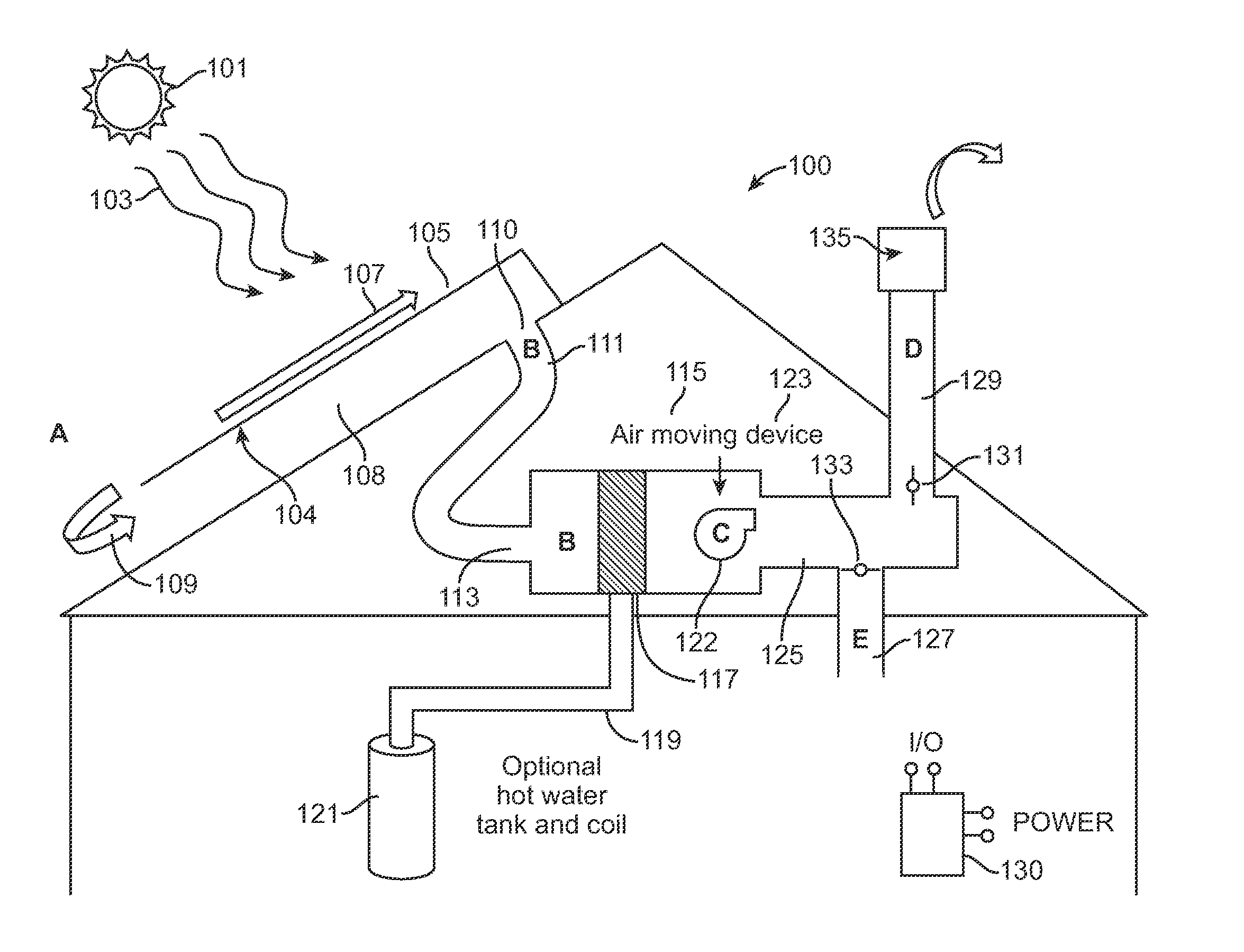
[0025]According to the present invention, techniques related to operation of a thermal solar system are provided. More particularly, the present invention provides a method and system for using a reverse flow configuration to remove thermal energy from a motor device configured for a thermal solar system. Merely, by way of example, the present invention has been applied to a thermal solar module configured on a building structure, but it would be recognized that the invention has a much broader range of applications.

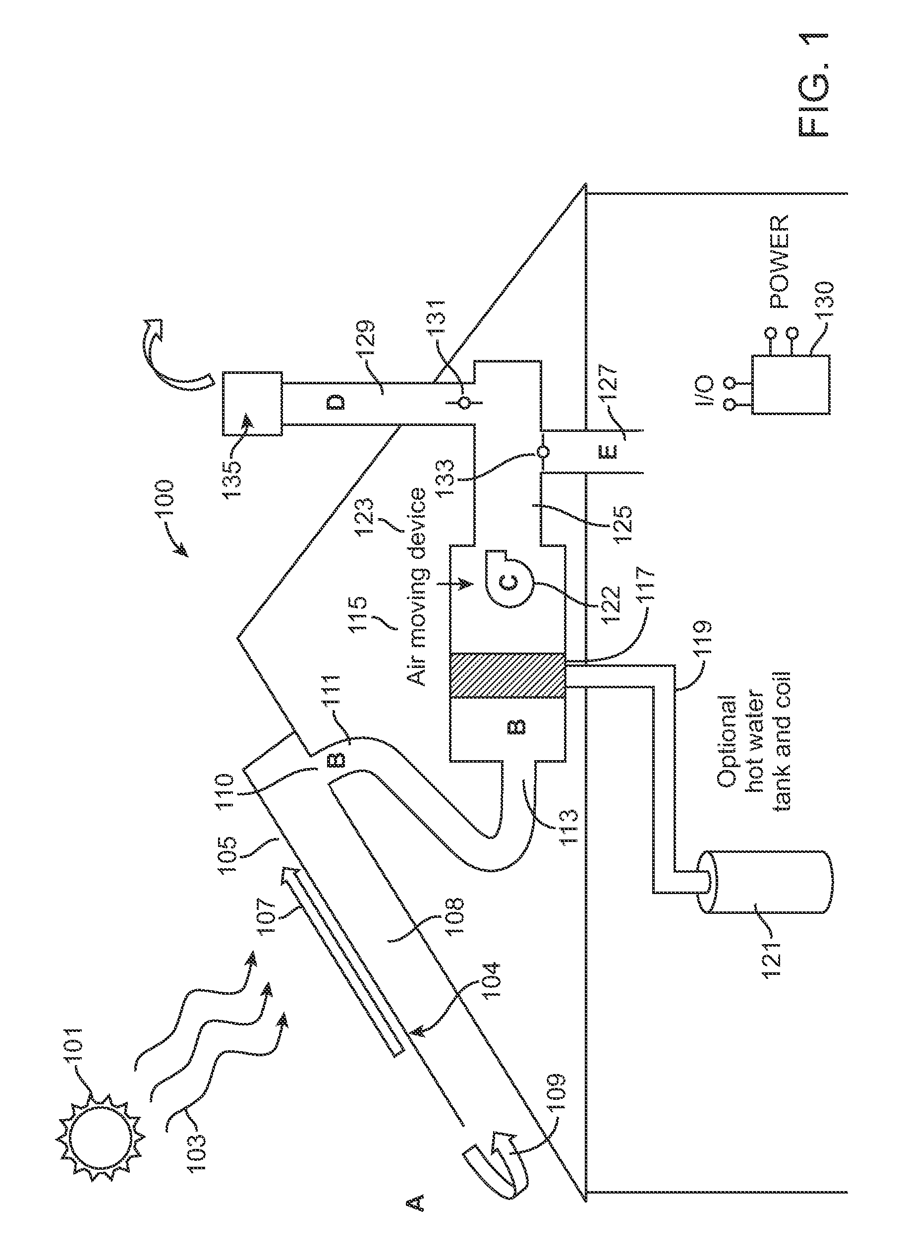
[0026]FIG. 1 is a simplified side view diagram of a thermal solar system according to an embodiment of the present invention. This diagram is merely an example, which should not unduly limit the scope of the claims herein. One of ordinary skill in the art would recognize other variations, modifications, and alternatives. As shown, the thermal solar system 100 includes a plurality of thermal modules spatially configured as an N by M array, where N is an integer greater th...


PUM


Abstract

A solar energy system. The system includes a thermal solar system comprising a plurality of thermal modules spatially configured as an N by M array. In a specific embodiment, the plurality of thermal modules are configured to form an aperture region and a backside region. The system has an air moving device comprising a drive device coupled to a blower device. In a specific embodiment, the drive device is spatially disposed within a fluid drive region. The system has a controller operably coupled to the air moving device. The controller is configured to operate the blower device in a first direction to cause fluid flow from at least the fluid flow intake region to the fluid flow exit region and to maintain a temperature of no greater than about 200 Degrees Fahrenheit within the fluid drive region by at least changing the first direction of operation of the blower device to a second direction to cause fluid from a third region to flow into the fluid drive region to initiate removal of thermal energy from the fluid drive region, which prevents the drive device from overheating.

Description

CROSS-REFERENCES TO RELATED APPLICATIONS[0001]This application claims priority to U.S. Provisional Application No. 61 / 141,642, filed Dec. 30, 2008, commonly assigned, and incorporated by reference for all purpose herein.BACKGROUND OF THE INVENTION[0002]The present invention relates to operation of a thermal solar system. More particularly, the present invention provides a method and system for using a reverse flow configuration to remove thermal energy from a motor device configured for a thermal solar system. Merely, by way of example, the present invention has been applied to a thermal solar module configured on a building structure, but it would be recognized that the invention has a much broader range of applications.[0003]Over the past centuries, the world population of human beings has exploded. Along with the population, demand for resources has also grown explosively. Such resources include raw materials such as wood, iron, and copper and energy, such as fossil fuels, includ...

Claims


Application Information

Patent Timeline
Patent Type & Authority Patents(United States)
IPC IPC(8): F24J2/04
CPCF24J2/045F24J2/402Y02B10/20Y02E10/44F24S20/67F24S50/40Y02E10/40Y02A30/60
Inventor ALBRITTON, CHARLES WADE
Owner FTC SOLAR INC
Why Eureka
Try Eureka