
Manufacturing method for stator structure and micromotor having the same

a stator and micromotor technology, applied in the manufacture of stator/rotor bodies, magnets, magnetic bodies, etc., can solve the problems of inability to effectively reduce the assembling time and flow of the motor, the processing of stamping, bending and winding may have considerable difficulty in manufacturing, and the effect of avoiding the alignment problem during assembly

Active Publication Date: 2013-02-19
METAL INDS RES & DEV CENT
View PDF7 Cites 1 Cited by
  • Summary
  • Abstract
  • Description
  • Claims
  • Application Information

AI Technical Summary

Benefits of technology

The FPC-based stator structure simplifies manufacturing, reduces costs, enhances precision in rotation position accuracy, and miniaturizes the motor by integrating all electrical elements within the motor's inner space, eliminating the need for additional detecting elements and facilitating high-precision control without increasing size.

Problems solved by technology

However, in stamping, bending and winding processes, due to lots of upper and lower pole plates and great length for winding, the processing of stamping, bending and winding may have considerable difficulty in manufacturing.
In addition, it is difficult to further reduce a size of the micromotor.
Therefore, it is unable to effectively reduce an assembling time and flow of the motor.
Nevertheless, the installation of the position encoder or the Hall devices will add more steps in the assembling procedure of the micromotor and will in turn spend more manufacturing man-hours and cost.
Furthermore, as each element is not aligned easily, it will further affect yields of the micromotor.

Method used


Image

  • Manufacturing method for stator structure and micromotor having the same
  • Manufacturing method for stator structure and micromotor having the same
  • Manufacturing method for stator structure and micromotor having the same

Examples


Embodiment Construction

[0026]In order to provide a further understanding to purposes, structural features, and functions of the present invention, detailed description is given below through related embodiments and drawings.

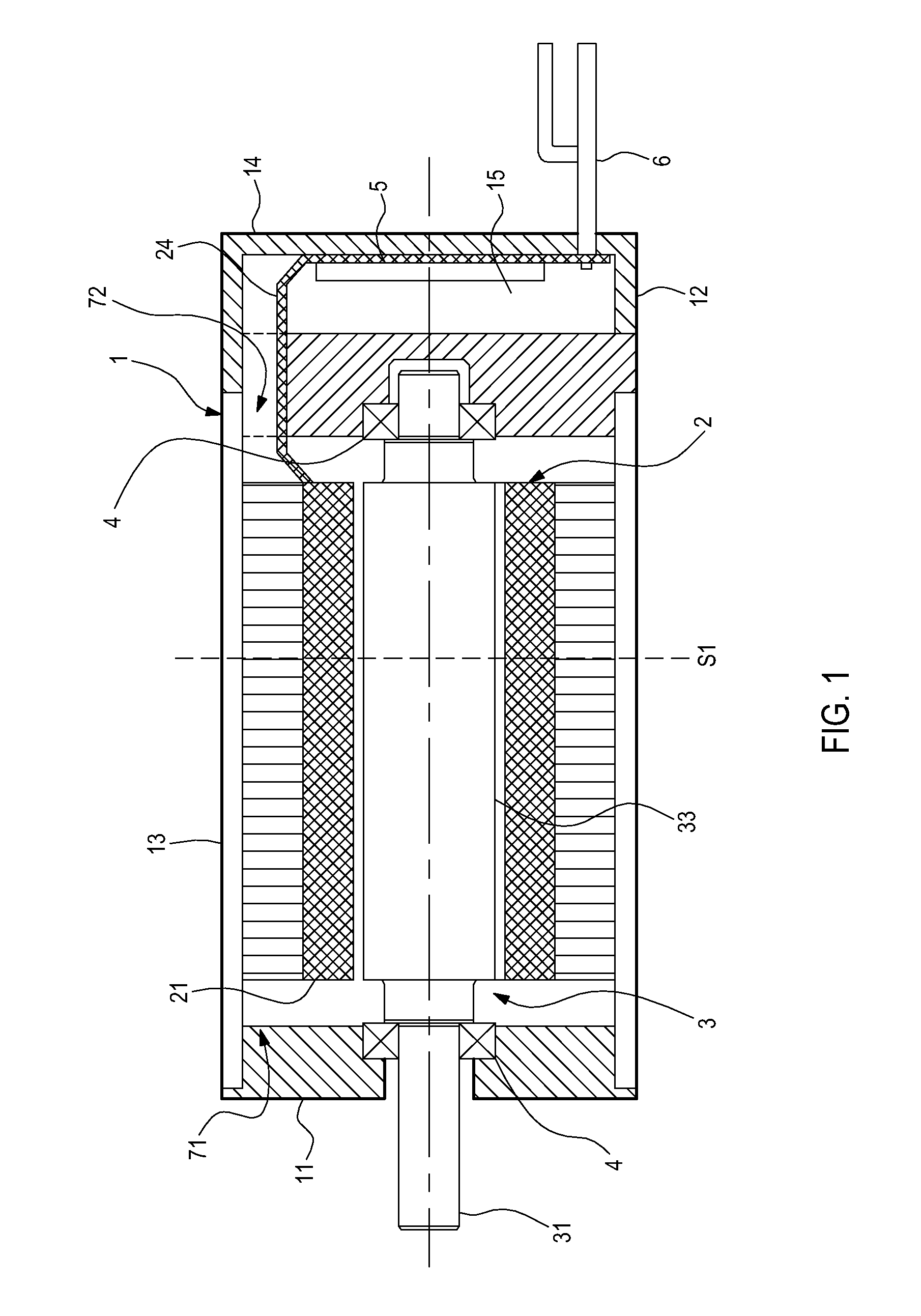
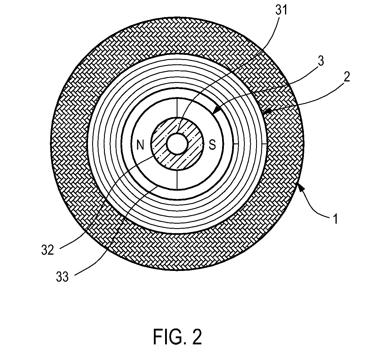
[0027]Referring to FIGS. 1 to 4B at the same time, FIG. 1 shows a perspective view of an embodiment of a micromotor of the present invention, FIG. 2 shows a cutaway view of the micromotor in FIG. 1 along a cutting line S1, FIGS. 3A to 3C show perspective views of three embodiments of different stator structures of the present invention, FIG. 4A shows a perspective view of a stator 2b of an embodiment of the present invention along a cutting line S2 and FIG. 4B shows a perspective view of a stator 2c of an embodiment of the present invention along a cutting line S3. As shown in FIG. 1, the micromotor includes three parts which are a rotor 3, a stator 2 and a case 1 disposed outward in a radial direction.

[0028]Referring to FIG. 1 and FIG. 2, the rotor 3 is constituted by a shaft 31, a ma...


PUM

PropertyMeasurementUnit
flexibleaaaaaaaaaa
sizeaaaaaaaaaa
magnetic thrust forceaaaaaaaaaa

Abstract

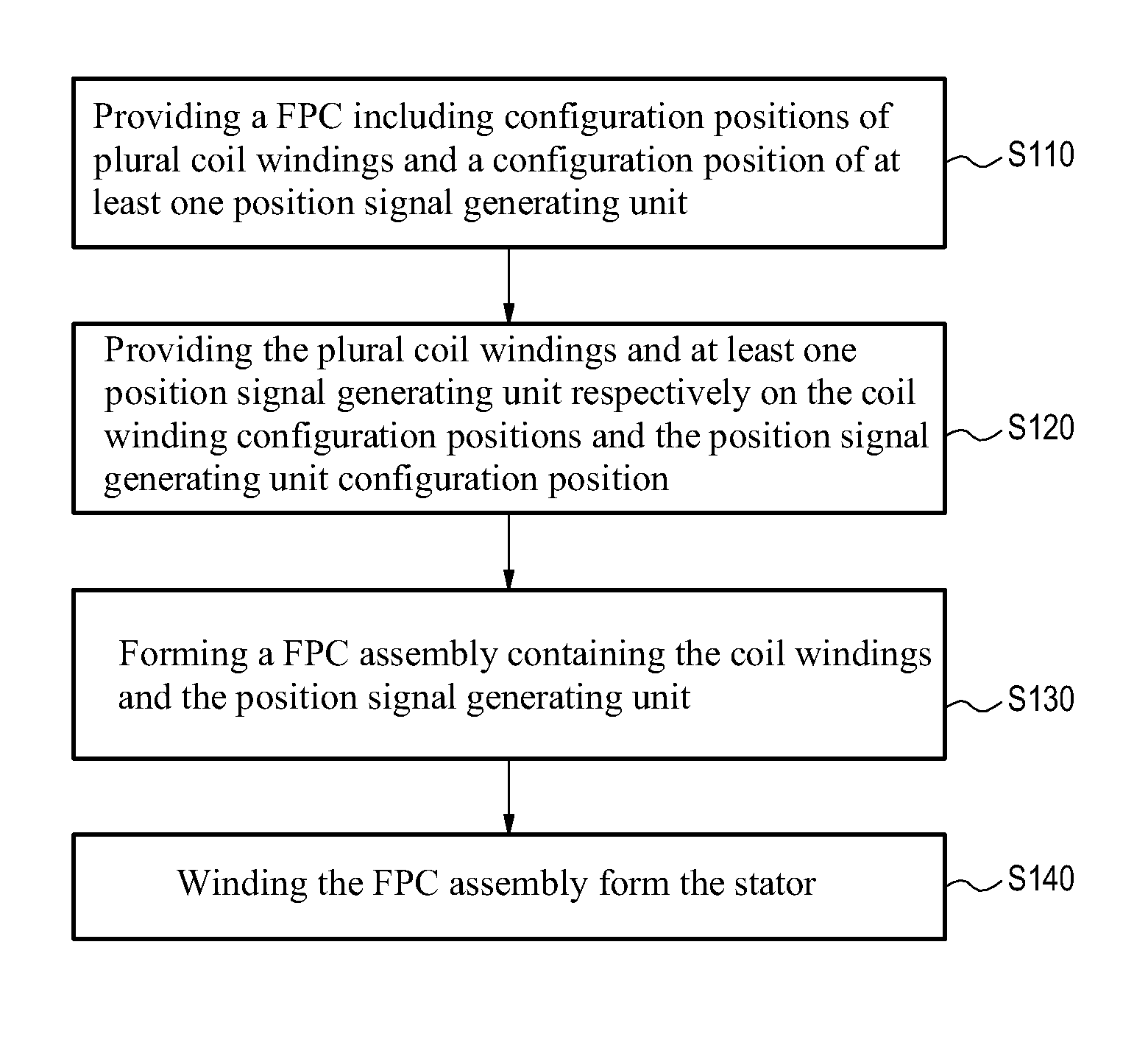
A manufacturing method for a stator structure and a micromotor having the same. The method includes: providing a flexible printed circuit (FPC) on which configuration positions of coil windings and a configuration position of at least one position signal generating unit are formed, wherein the FPC is further provided with an interface part; disposing the coil windings and the position signal generating unit on the coil winding configuration positions and the position signal generating unit configuration position, respectively, wherein the interface part is further provided with a connector pattern which is electrically coupled with the coil windings and the position signal generating unit; forming a FPC assembly including the coil windings and the position signal generating unit; and winding the FPC assembly to form the stator. The stator is applied in a micromotor in which a rotor, the stator and a case are disposed outward in a radial direction.

Description

CROSS-REFERENCE TO RELATED APPLICATION[0001]This application claims the benefit of Taiwan Patent Application No. 098127425, filed on Aug. 14, 2009, which is hereby incorporated by reference for all purposes as if fully set forth herein.BACKGROUND OF THE INVENTION[0002]1. Field of Invention[0003]The present invention relates to a stator structure and a micromotor having the same, and more particularly to a micromotor and a manufacturing method therefor, wherein the stator structure is constituted by a flexible printed circuit (FPC) configured with the required electrical elements of the micromotor.[0004]2. Related Art[0005]In a conventional micromotor, a stator includes primarily a magnetoconductive housing which is provided with upper and lower pole plates and is formed by stamping, bending and welding a magnetoconductive material in sheet form; and coil windings which are configured on the magnetoconductive housing. However, in stamping, bending and winding processes, due to lots o...

Claims


Application Information

Patent Timeline
Patent Type & Authority Patents(United States)
IPC IPC(8): H02K15/04
CPCH02K3/26H02K5/225Y10T29/49012Y10T29/49071Y10T29/49009H02K11/0031H02K11/225
Inventor YAN, GUO-JHIHWANG, JING-HUIYAN, SHENG-ZHANHUANG, GUANG-MIAOHSU, LIANG-YITSAI, MI-CHING
Owner METAL INDS RES & DEV CENT
Learn More