
Ion trap

a technology of ion traps and ion traps, applied in the field of ion traps, can solve the problems of complex and expensive, and achieve the effect of simplifying the fabrication of ion traps

Active Publication Date: 2013-01-29
THE UNIV OF SUSSEX
View PDF2 Cites 3 Cited by
  • Summary
  • Abstract
  • Description
  • Claims
  • Application Information

AI Technical Summary

Benefits of technology

The patent describes a new design for an ion trap that makes it easier to fabricate and provides better control over the electrical potential. The electrodes are arranged in a flat pattern, and the directions of the electric and magnetic fields can be carefully defined to trap ions. The electrodes are designed with a guard electrode on each side, which helps to create a stable ion position and shape the electric field. The electrodes are also arranged close to the magnetic field generator, which simplifies the fabrication process and makes the ion trap more portable. The magnetic field generator comprises a row of magnetic elements to ensure homogeneous magnetic field. Overall, this design improves the performance of the ion trap and makes it easier to trap ions.

Problems solved by technology

This places constraints in the design of a conventional Penning trap and its variants, generally making them complex and expensive.

Method used


Image

  • Ion trap
  • Ion trap
  • Ion trap

Examples


Embodiment Construction

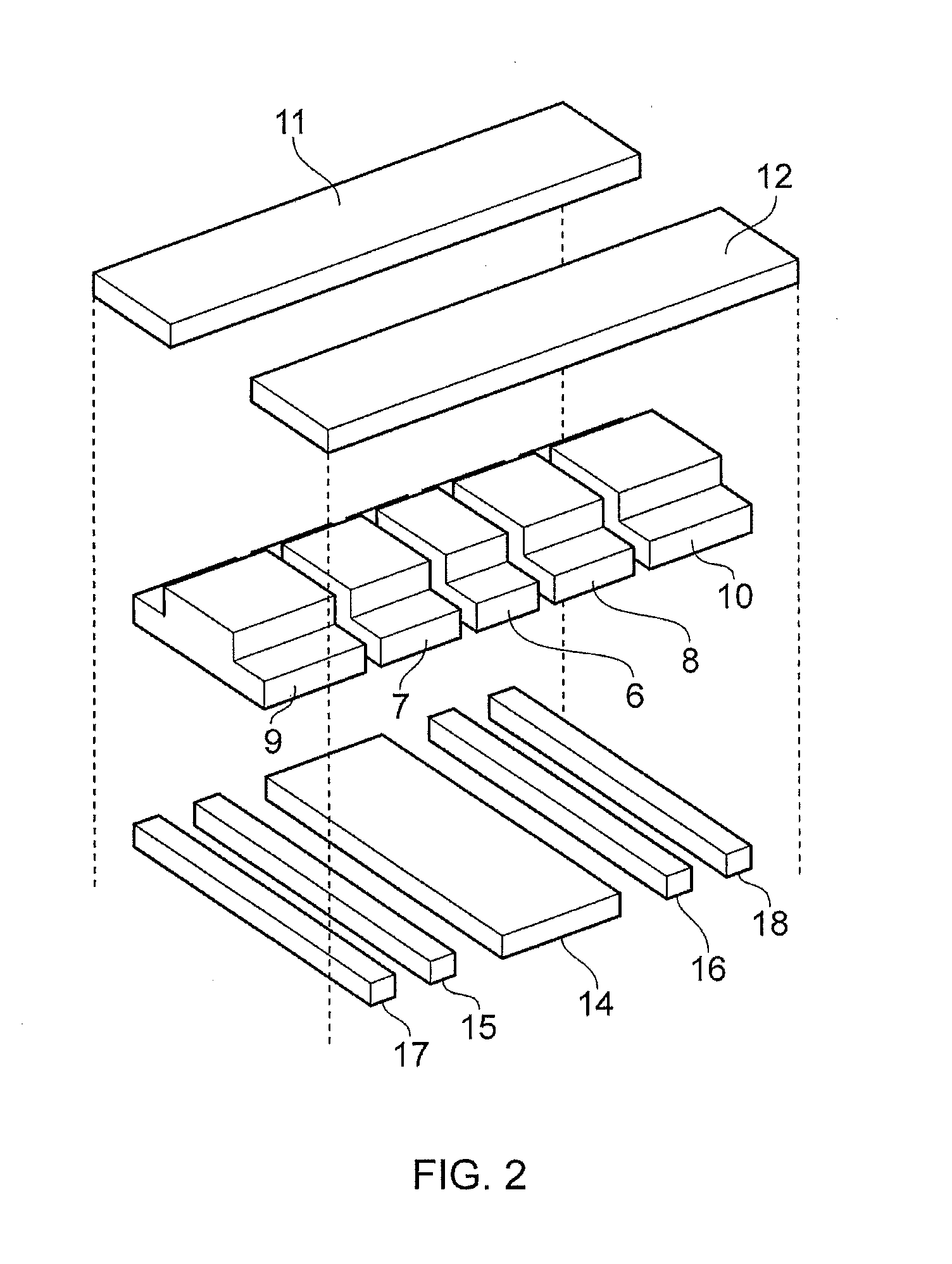
[0043]Referring to FIGS. 1 and 2, an ion trap 1 comprises a magnetic field generator 2 and an electrode array 3 provided on a substrate 4. The ion trap 1 is effectively a variant of a conventional Penning trap, and can be referred to as a Penning trap in the context of the general principles of its operation, although not in terms of its specific structure, which differs significantly. The term “coplanar waveguide Penning trap” has been coined to describe the ion trap 1.

[0044]It should be noted that the ion trap 1 is described in the context of a trap for negatively charged ions, in particular an electron, for simplicity. However, the skilled person will recognise that the trap can equally be used for trapping positively charged ions by reversing the polarity of the electrode array 3.

[0045]In this embodiment, the substrate 4 is a dielectric material suitable for forming a microwave transmission line, for example for microwaves in the range 3 to 30 GHz. Suitable materials are, for ex...


PUM


Abstract

An ion trap 1 comprises a magnetic field generator 2 arranged to generate a magnetic field and an array 3 of electrodes arranged to generate an electrostatic field including a turning point in electrical potential at a location where the magnetic field is substantially homogeneous. The array of electrodes 3 is planar and parallel to the direction of the magnetic field at the location, with the result that the ion trap can be described as a coplanar waveguide Penning trap.

Description

FIELD OF THE DISCLOSURE[0001]The disclosure relates to an ion trap, and to a mass spectrometer and to a quantum electrodynamic circuit incorporating the ion trap.BACKGROUND TO THE DISCLOSURE[0002]An ion trap is an apparatus used to confine or isolate a charged particle, such as an electron. One such apparatus is known as a Penning trap. A Penning trap uses a magnetic field and an electrostatic field together to trap a charged particle. The magnetic field causes the charged particle to perform a rotational movement with the direction of the magnetic field being the axis of the rotation. This effectively confines the charged particle to a plane normal to the direction of the magnetic field. The electrostatic field is arranged to confine the charged particle at a location along the direction of the magnetic field, by providing a potential well for the particle at the desired location.[0003]In order for a Penning trap to confine a charged particle effectively and to be useful for perfor...

Claims


Application Information

Patent Timeline
IPC IPC(8): H01J49/38
CPCH01J49/422B82Y10/00H01J49/20H01J49/38H01J49/0031H01J49/0018
Inventor VERDU GALIANA, JOSE LUIS
Owner THE UNIV OF SUSSEX
Learn More