
Wide angle HDTV endoscope

a wide angle, endoscope technology, applied in the field of endoscopes, can solve the problems of inability to meet, excessively high cost of rectangular lenses, design usually continues to have optical image quality problems, etc., and achieve the effect of increasing the field of view of the endoscop

Active Publication Date: 2013-01-29
STRYKER CORP
View PDF41 Cites 83 Cited by
  • Summary
  • Abstract
  • Description
  • Claims
  • Application Information

AI Technical Summary

Benefits of technology

This patent describes an endoscope that can capture images from a wider angle than typical endoscopes. It does this by using two rounded optical channels that send images to an image sensor. The images are then fitted to a rectangular sensor to increase the field of view. This allows for a wider view of the endoscope and the surrounding area.

Problems solved by technology

Thus, this arrangement shows a problem that already existed with 4:3 aspect ratio imaging elements 44.
The mismatch, however, becomes much more unacceptable and undesirable with the use of a HD imaging device 46 having a 16:9 aspect ratio as shown in FIG. 4.
Besides the excessively high cost of manufacturing rectangular lenses, such designs usually continue to have optical image quality problems due to the natural corners of the rectangular lens elements no matter what kind of coating is provided for the rectangular lenses.
In fact, perfectly coating such lens corners in practical systems is almost impossible.

Method used


Image

  • Wide angle HDTV endoscope
  • Wide angle HDTV endoscope
  • Wide angle HDTV endoscope

Examples


Embodiment Construction

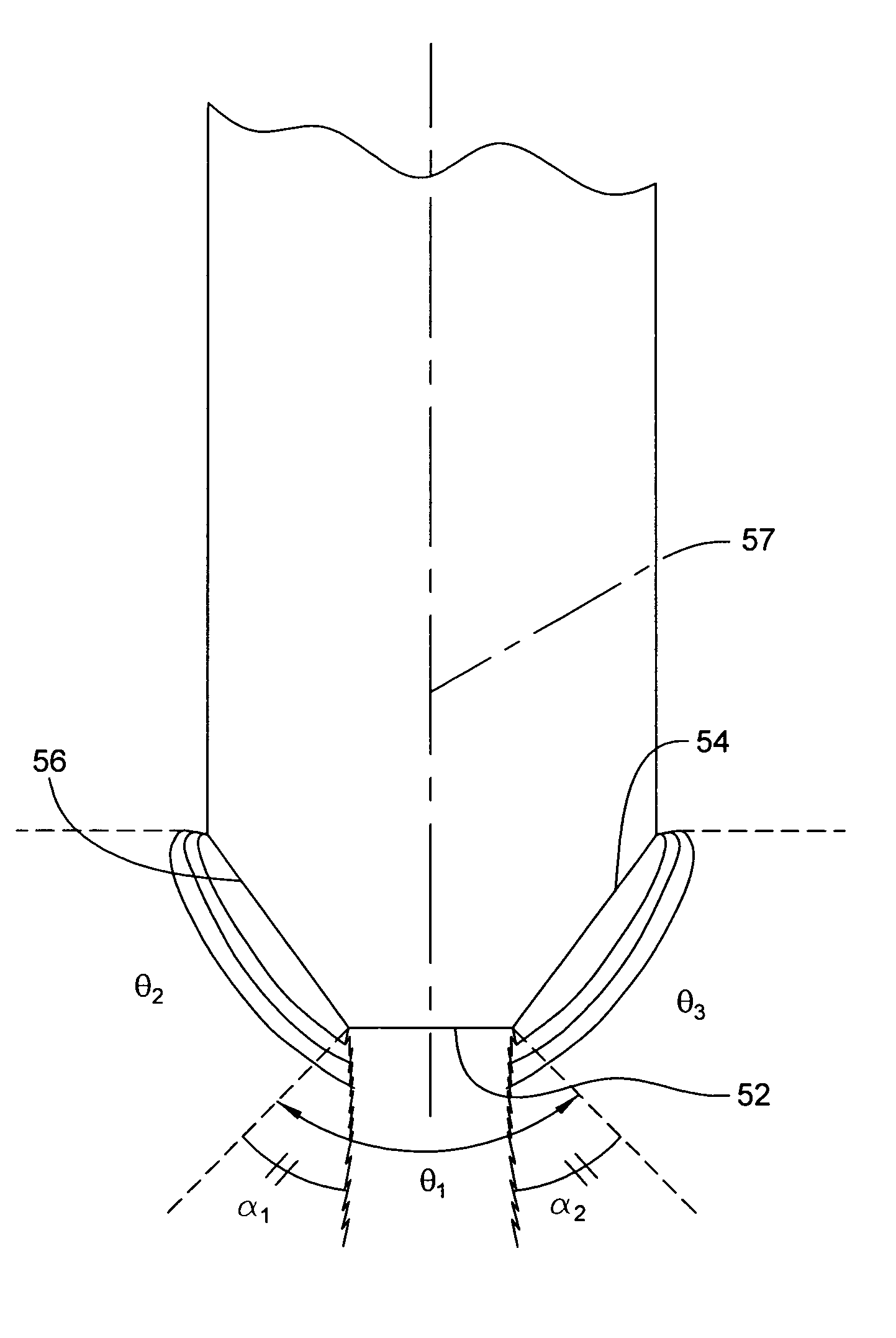
[0031]FIGS. 5-9 illustrate one embodiment of the invention. In this embodiment, the distal tip end 48 of the endoscope 50 has a flat circular tip and is rounded or tapered in a longitudinal direction to join with a cylindrical portion of the endoscope 50. As in the prior art, the endoscopic system includes a fiber optic cable 22 connected to external light source 20. A lens coupler 51 is provided at the proximal end of the endoscope 50. Further, the system includes a camera 14 having an image sensor 46 connected by a cable 18 to an image processing device 49.

[0032]A front view of the distal tip end 48 of the imaging endoscope 50 is shown in FIG. 6. The tip end 48 includes a first frontwardly directed central lens 52 and second and third sidewardly oriented lenses 54, 56 symmetrically provided on opposing sides of the center lens 52. While lenses 54, 56 appear elliptical in FIG. 6, the lenses 54, 56 are actually circular in shape, as is central lens 52. In FIG. 7, the lenses 54, 56 a...


PUM


Abstract

A wide angle HDTV endoscope includes at least two optical imaging channels. Lenses close each channel at the distal end of the endoscope. The imaging channels each have a different field of view in complementary directions, and have overlapping or cross-over field of view areas. Received images are transmitted along the longitudinal axis of the imaging channels of the endoscope to a camera head that contains a wide screen image sensing device. An external light source provides the required lighting and an image processing device can provide necessary software algorithms to format the images and to control any overlapping or cross-over field of view areas to obtain a single display image. In another arrangement, optical blocking elements provided at the proximal end of the endoscope or within the imaging channels eliminate portions of one or more images from the imaging channels so that at the cross-over areas only a single image is provided to the imaging device.

Description

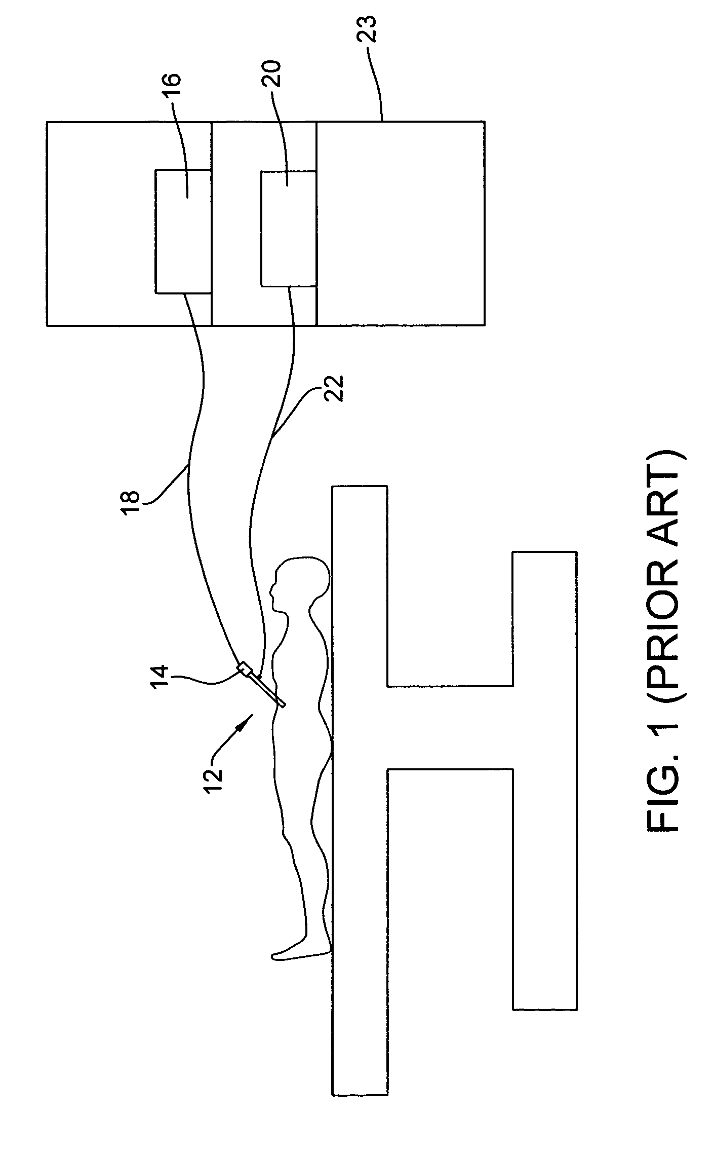
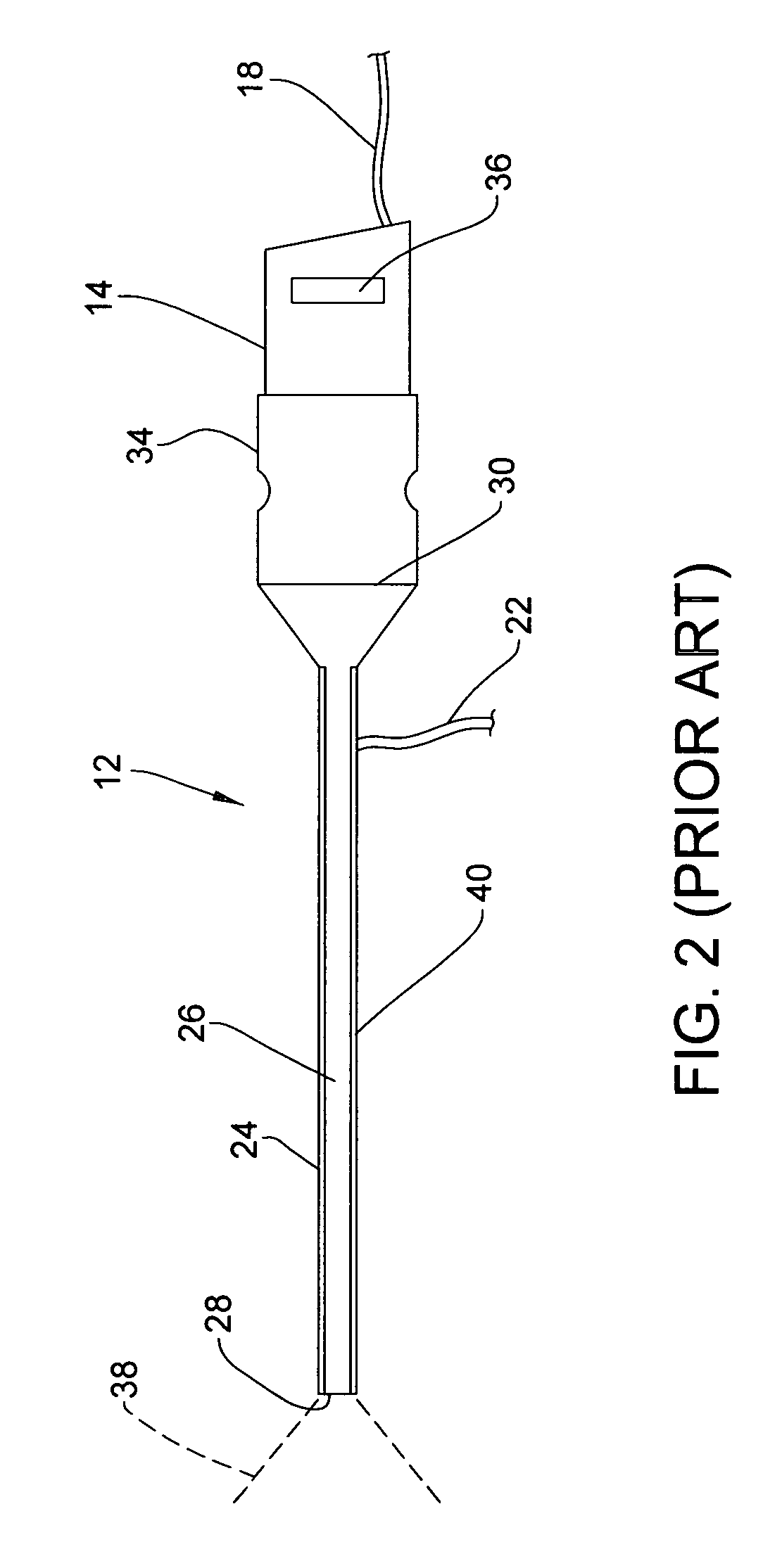
CROSS-REFERENCE TO RELATED APPLICATION[0001]This application claims the benefit of U.S. Provisional Application Ser. No. 61 / 007,002, filed Dec. 10, 2007, which is incorporated herein by reference in its entirety.FIELD OF THE INVENTION[0002]This invention relates to the endoscopy field, and primarily endoscopes used in minimally invasive surgeries. This invention allows a true wide screen endoscopic image to be created that is sent to a display screen to provide a 16:9 aspect ratio HDTV image with a wide angle view that shows more of an observed surface of an anatomical structure to viewers.BACKGROUND OF THE INVENTION[0003]In today's minimally invasive surgeries, imaging devices are used to help a surgeon visualize the interior of a patient's body. Depending on the type of procedure, an endoscope is typically inserted into the patient's abdominal area, knee joint, shoulder joint or some other part of the body that requires surgical treatment. As shown in prior art FIG. 1, the endosco...

Claims


Application Information

Patent Timeline
Patent Type & Authority Patents(United States)
IPC IPC(8): A61B1/06
CPCA61B1/0005A61B1/00096A61B1/00181A61B1/042H04N5/2254H04N5/23238H04N2005/2255H04N23/555H04N23/55H04N23/698
Inventor ERTAS, HASAN
Owner STRYKER CORP
Learn More