
Instrumentation ATS/TPS mitigation utilizing I/O data stream

Active Publication Date: 2013-01-22
ADVANCED TESTING TECH
View PDF36 Cites 10 Cited by
  • Summary
  • Abstract
  • Description
  • Claims
  • Application Information

AI Technical Summary

Benefits of technology

This patent describes a method for replacing old test instruments in an automated test system. The method allows the old instruments to continue to work while the new instruments are added. This allows multiple old instruments to be replaced within the same system. The method also uses procedures to replace single instructions replaced by context-sensitive solutions. This helps to reduce regression testing and ensures the new system works correctly.

Problems solved by technology

Since the inception of automated test systems or automated test equipment, engineers have struggled with managing the life expectancy of the overall test system (and component instruments) against the life expectancy of the electronic equipment being tested.
Early versions were typically company proprietary and often, no standard existed to guide interoperability of different products.
Today's solutions leverage commercial technology and standards through the use of what is often termed open architecture; however, these solutions don't readily apply themselves to legacy systems.
As the useful life of automatic test systems is extended, instruments in such automatic test systems invariably become obsolete and need to be replaced with newer instruments that may not function within the legacy ATS architecture.
For example, a new instrument may not have a compatible instruction set or communications interface to enable its use within the legacy automatic test system.
Additionally, the interdependence of the test program and the ATS instruments further compounds the problem of new instrument insertion, and typically requires test program changes.
These factors make it cost prohibitive to introduce new instruments into a legacy automatic test system.

Method used


Image

  • Instrumentation ATS/TPS mitigation utilizing I/O data stream
  • Instrumentation ATS/TPS mitigation utilizing I/O data stream
  • Instrumentation ATS/TPS mitigation utilizing I/O data stream

Examples


Embodiment Construction

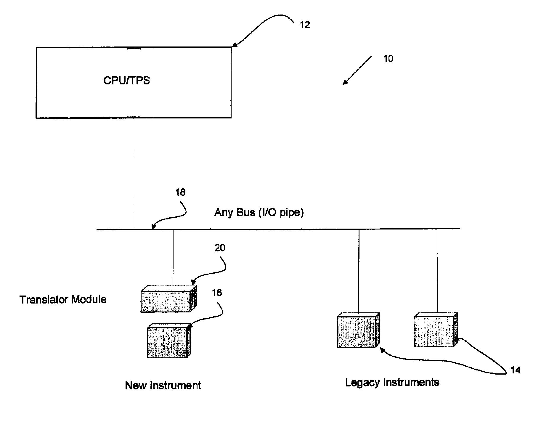
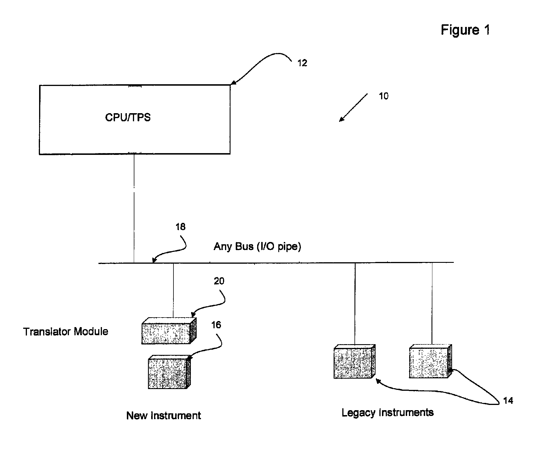
[0025]Referring to the accompanying drawings wherein like reference numerals refer to the same or similar elements, FIG. 1 illustrates the hierarchy of a system in accordance with the invention, i.e., a system of subsystems, which is designated generally as 10. The system of subsystems 10 includes one or more control systems 12 (only one of which is shown) which controls test instrument systems, including one or more legacy instruments 14 and a new instrument or set of instruments 16, all of which communicate with one another via a data conduit such as a bus 18 or other input / output pipe (I / O pipe). In accordance with the invention, a translator module 20 is coupled to the new instrument or set of instruments 16, e.g., an interface of the translator module 20 is connected to an interface of the new instrument or set of instruments 16. The translator module 20 is connected to the bus 18 and thus enables communication between the new instrument or set of instruments 16 and the control...


PUM


Abstract

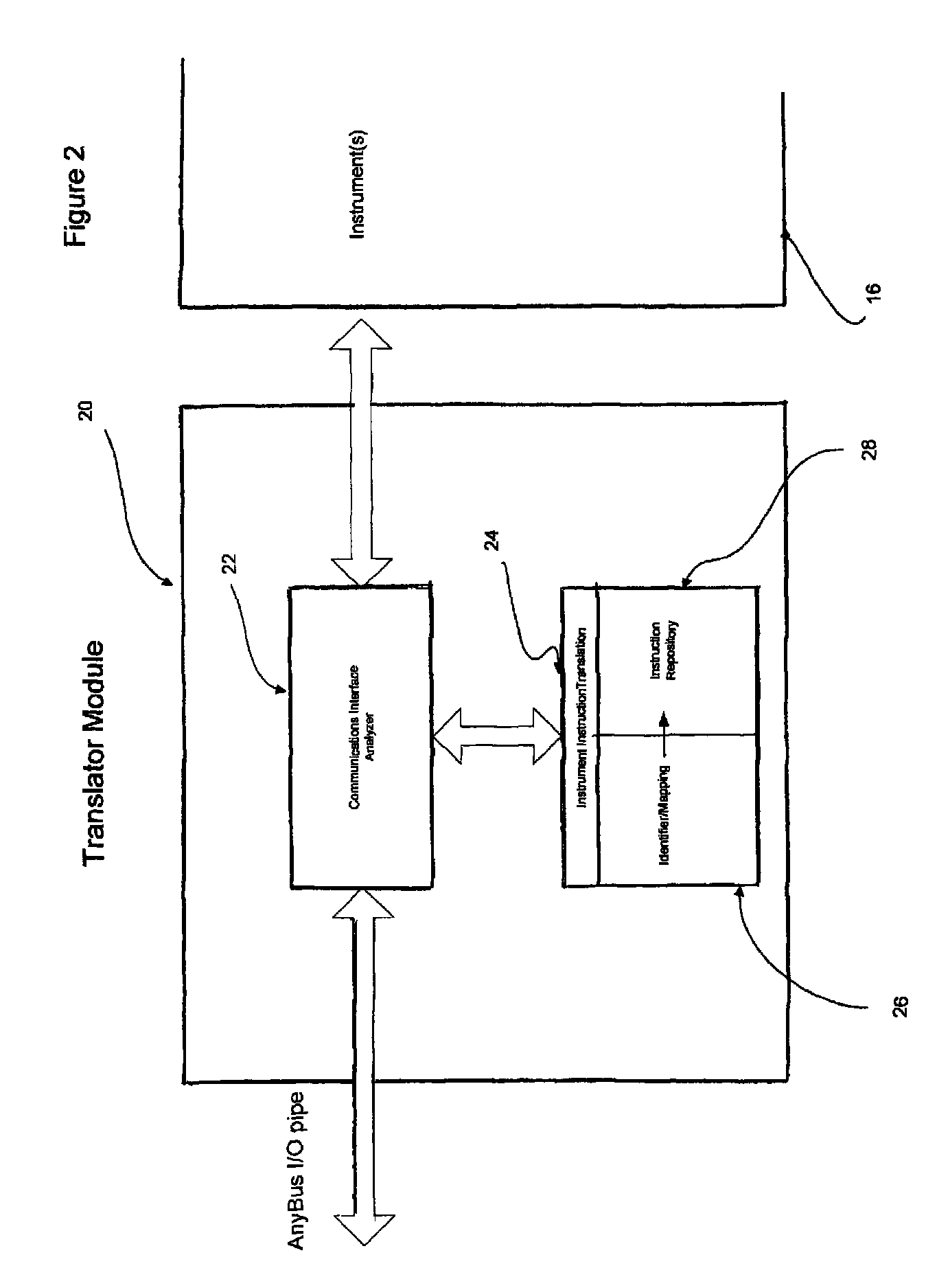
Methods and systems for obsolescence mitigation of electronic systems including hardware and software components, in particular methods and systems for managing obsolete instrument hardware and application software used in legacy Automated Test Systems (ATS) or Automatic Test Equipment (ATE). When one or more components of a test program set (TPS) has been rendered obsolete, migration to one or more replacement instruments without any impact to the TPS or other remaining legacy instruments in the ATE or ATS is obtained by a translator module interposed between the new instrument and the system bus for translating instructions for the obsolete instrument or set of instruments into instructions or procedures for the new instrument whereby the new instrument thus functions in the same manner as the obsolete instrument or set of instruments.

Description

CROSS REFERENCE TO RELATED APPLICATION[0001]This application claims priority under 35 U.S.C. §119(e) of U.S. provisional patent application Ser. No. 60 / 881,075 filed Jan. 18, 2007, the entire contents of which are incorporated by reference herein.FIELD OF THE INVENTION[0002]The present invention relates generally to methods and systems for obsolescence mitigation of electronic systems including hardware and software components, and more particularly to methods and systems for managing obsolete instrument hardware and application software used in legacy Automated Test Systems (ATS) or Automatic Test Equipment (ATE).[0003]The present invention also relates generally to methods and tools used to enable migration to replacement instruments without any impact to Test Program Sets (TPS).BACKGROUND OF THE INVENTION[0004]Since the inception of automated test systems or automated test equipment, engineers have struggled with managing the life expectancy of the overall test system (and compon...

Claims


Application Information

Patent Timeline
IPC IPC(8): G06F9/44G06F9/45
CPCG06F8/40
Inventor SPINNER, ROBERTLEIPPE, WILLIAM HAROLDMCKENNA, JAMESFOX, TIMOTHY
Owner ADVANCED TESTING TECH
Learn More