
Illumination device

a technology of a slit and a lens, which is applied in the direction of instruments, lighting and heating apparatus, lenses, etc., can solve the problems of reducing the ease of use, reducing the convenience of reading books, and the slit device described is less convenient to read, so as to achieve convenient reading, convenient reading, and sufficient magnification

Inactive Publication Date: 2013-01-15
SIGNIFY HLDG BV
View PDF17 Cites 6 Cited by
  • Summary
  • Abstract
  • Description
  • Claims
  • Application Information

AI Technical Summary

Benefits of technology

[0004]Thus, the invention has for its object to eliminate the above mentioned disadvantages. In particular, it is an object of the invention to provide an efficient and cheap illumination device, which combines a sufficient magnification for convenient reading with a small overall thickness.

Problems solved by technology

Unfortunately, the described device is less convenient for reading books, which possess in general a curved reading area.
In addition, the device is a relatively thick wedge shaped light guide where the thickness results in relatively high weight and this reduces ease of use.
It also results in a relatively high mechanical stiffness making it very difficult to bend the device over a curved reading area.
Unfortunately, such magnification elements possess a relatively small magnification.
The disadvantage of such bar magnifier is their weight and the distortion of the image.

Method used


Image

  • Illumination device
  • Illumination device
  • Illumination device

Examples


Embodiment Construction

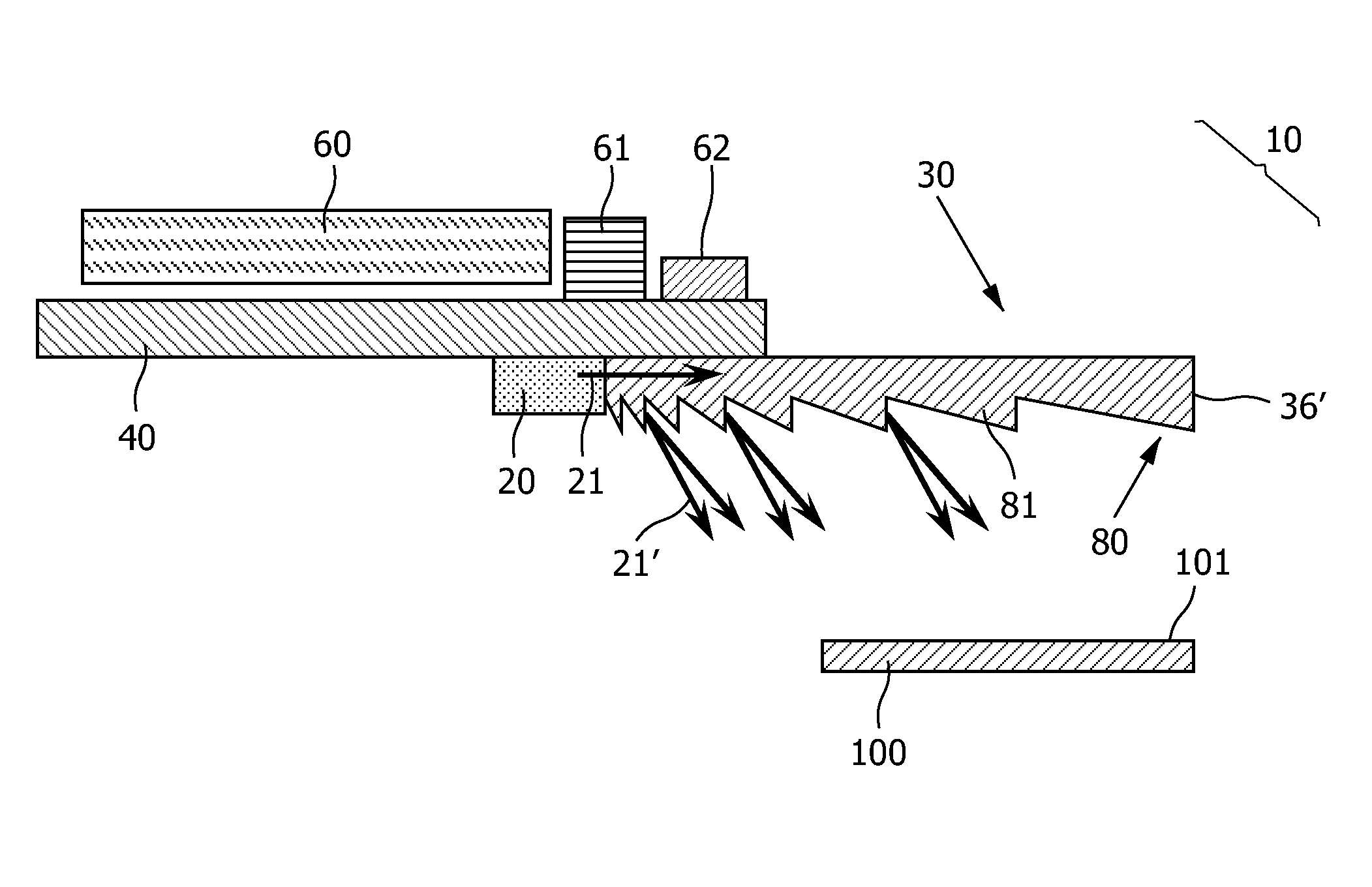
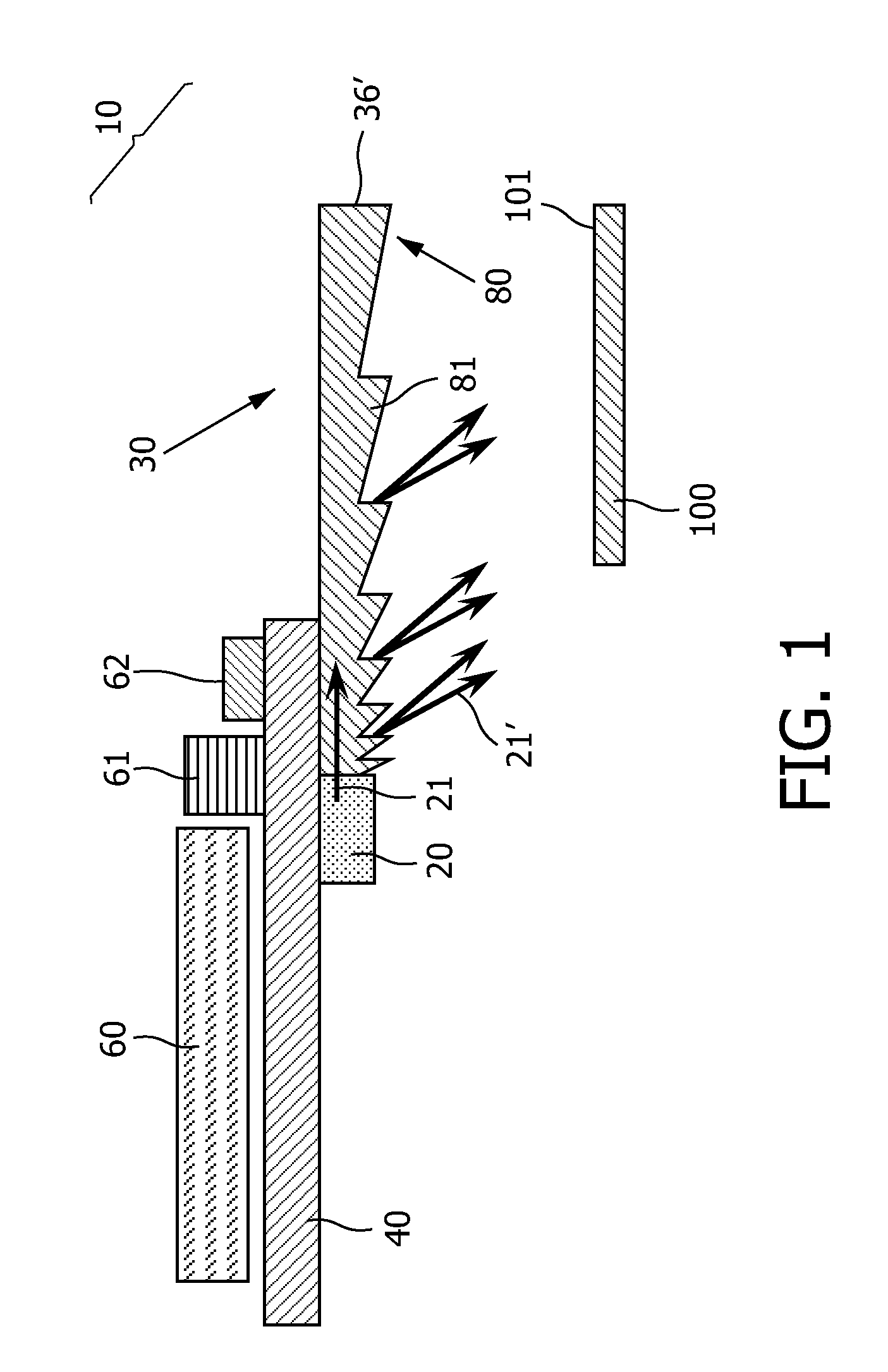
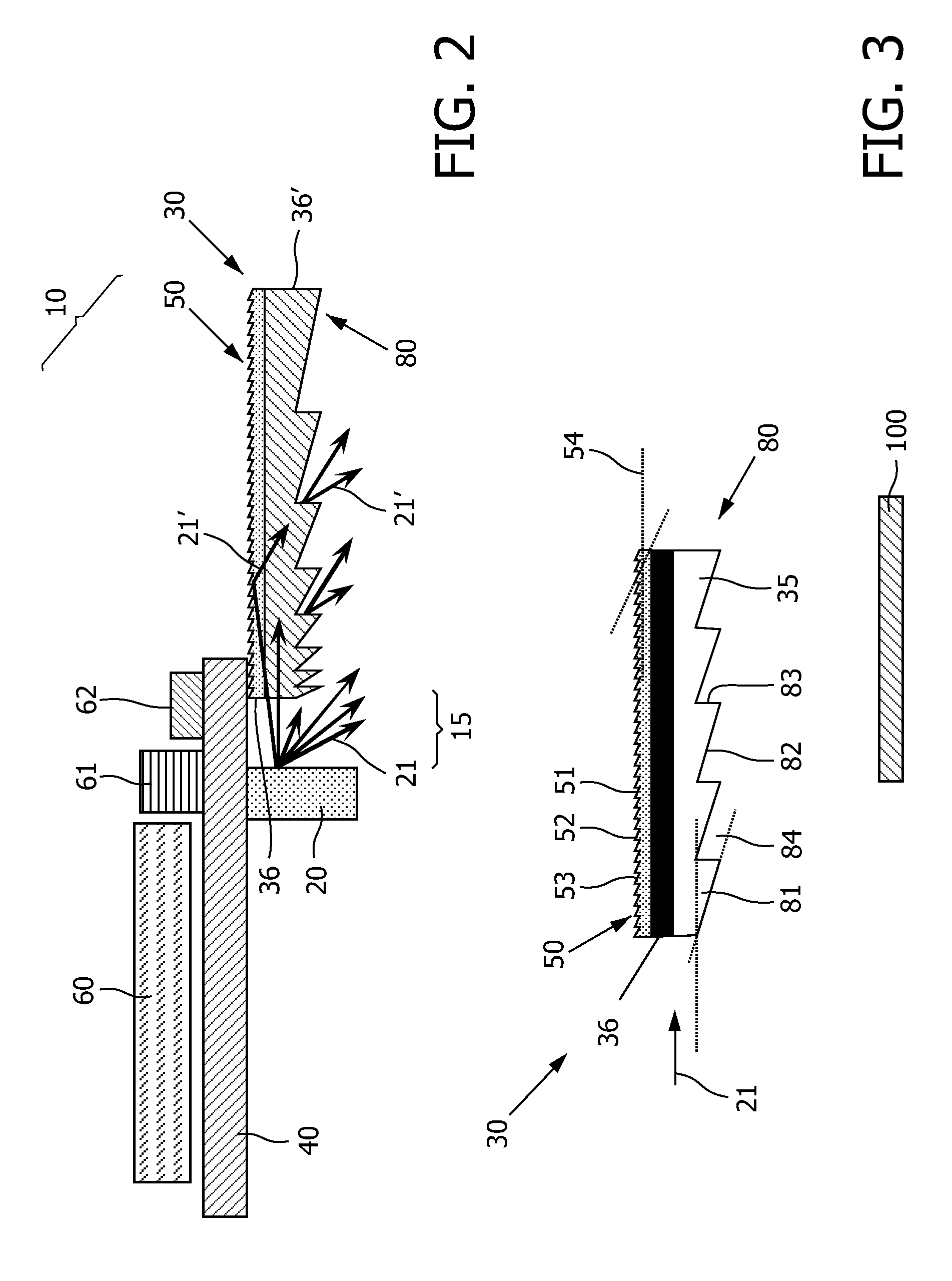
[0048]In FIG. 1 an illumination device 10 for illuminating a surface 101 of an object 100 is shown. The illumination device 10 comprises a lighting element 20 and an illuminating body 30. The lighting element 20 is arranged subjacent to a housing element 40, which supports the illuminating body 30. In the shown embodiment the illumination device 10 is a reading light, used to illuminate the generally flat surface 101 of the object 100, such as a page of a book lying subjacent to the illuminating body 30. To optically magnify the surface 101 the illumination body 30 comprises a surface pattern 80 forming a Fresnel-type lens. Such Fresnel-type lenses can achieve a large magnification without the need of a rather thick illumination body 30.

[0049]The lighting element 20 is a LED, which injects the artificial light 21 into the illuminating body 30. The lighting element 20 is connected with the holding element 40, which may be a printed circuit board (PCB). Such printed circuit boards are...


PUM


Abstract

The invention relates to an illumination device (10) for illuminating a surface (101), with at least one lighting element (20) and an illuminating body (30), wherein the lighting element (20) emits an artificial light (21,21), a housing element (40) comprises the lighting element (20) and supports the illuminating body (30), the illuminating body (30) comprises a transparent light conductive material suitable to illuminate the surface (101) lying subjacent. The invention discloses, that the illuminating body (30) comprises a surface pattern (80), forming a Fresnel-type lens to optically magnify the surface (101).

Description

FIELD OF THE INVENTION[0001]This invention relates to an illumination device for illuminating a surface, with at least one lighting element and an illuminating body, wherein the lighting element emits an artificial light, a housing element comprises the lighting element and supports the illuminating body, the illuminating body comprises a transparent light conductive material and is generally overlying the surface, being illuminated.BACKGROUND OF THE INVENTION[0002]In the U.S. Pat. No. 6,951,403 B2 a device for illuminating a generally flat surface is described, which comprises a battery operated light source contained within a housing to which a transparent light conductive illuminating body is mounted. The device may be placed with the illuminating body over a book or other flat surfaces for illuminated viewing through the transparent illuminating body. The illuminating body is tapered in a wedge shape to deflect the conducted light onto the underlying surface. Unfortunately, the ...

Claims


Application Information

Patent Timeline
Patent Type & Authority Patents(United States)
IPC IPC(8): F21V7/04F21Y101/00
CPCG02B6/0038G02B6/0055G02B25/02B42D3/18G02B3/08Y10S362/80
Inventor CENNINI, GIOVANNICORNELISSEN, HUGO JOHANRONDA, CORNELIS REINDERLIU, YADONG
Owner SIGNIFY HLDG BV
Learn More