
Illumination device

a technology of a slit lamp and a slit lamp, which is applied in the direction of spectral modifiers, electric circuit arrangements, and power-in-place devices, can solve problems such as disturbing others, and achieve the effect of convenient light level and efficient and cheap

Inactive Publication Date: 2012-12-25
SIGNIFY HLDG BV
View PDF20 Cites 2 Cited by
  • Summary
  • Abstract
  • Description
  • Claims
  • Application Information

AI Technical Summary

Benefits of technology

The device provides uniform and pleasant lighting on curved surfaces, is lightweight and compact, and can be easily bent over a reading area, reducing power consumption and minimizing disturbance to others.

Problems solved by technology

If a normal light source is used for reading e.g. a book, it may disturb others, especially if used in bedrooms.

Method used


Image

  • Illumination device
  • Illumination device
  • Illumination device

Examples


Embodiment Construction

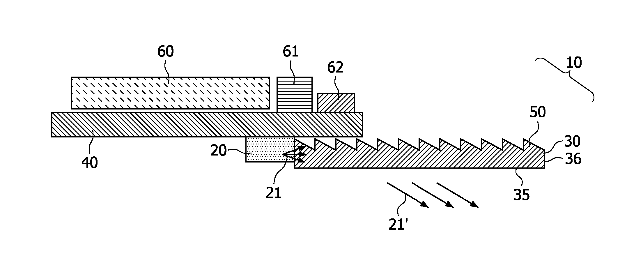
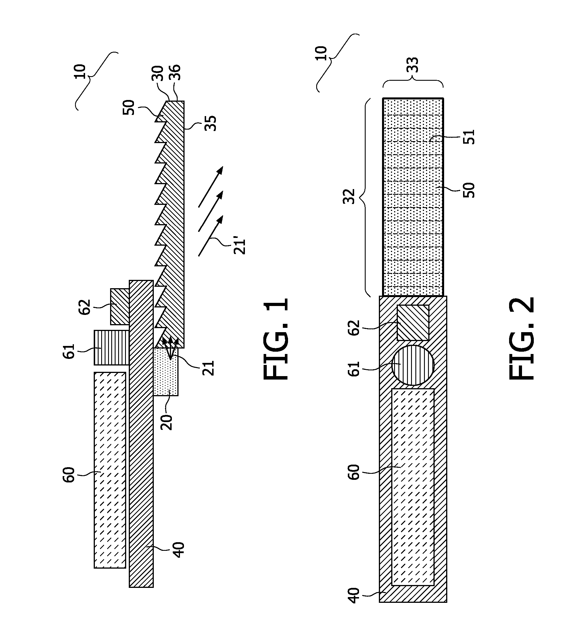
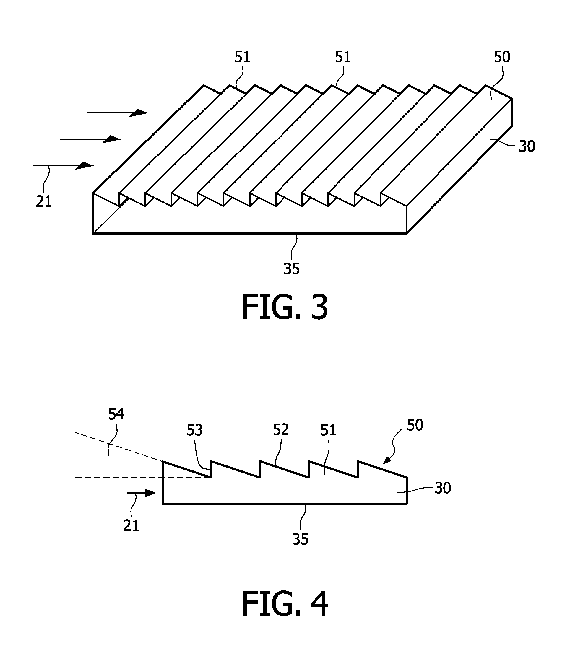
[0048]In FIG. 1 an illumination device 10 for illuminating a surface is shown. The illumination device 10 comprises a lighting element 20 and an illuminating body 30. The lighting element 20 is arranged subjacent to a housing element 40, which supports the illuminating body 30. In the shown embodiment the illumination device 10 is a reading light, used to illuminate a generally flat surface, such as a page of a book, lying subjacent to the illuminating body 30. To reduce the possibility of disturbing other people, the emission of artificial light 21 beyond the surface, being illuminated, has to be minimal. To achieve this aim the illuminating body 30 comprises a light extraction layer 50, configured to receive and to deflect the artificial light 21 from the lighting element 20 onto the surface.

[0049]The lighting element 20 is a LED, which injects the artificial light 21 into the illuminating body 30. The lighting element 20 is connected with the holding element 40, which may be a pr...


PUM


Abstract

The invention relates to an illumination device (10) for illuminating a surface, with a lighting element (20) and an illuminating body (30), wherein the lighting element (20) emits an artificial light (21,21′), a housing element (40) comprises the lighting element (20) and supports the illuminating body (30), the illuminating body (30) comprises a transparent light conductive material and is generally overlying the surface, being illuminated. The invention discloses, that the illuminating body (30) comprises a light extraction layer (50), configured to receive and to deflect the artificial light (21,21′) from the lighting element (20) onto the surface.

Description

FIELD OF THE INVENTION[0001]This invention relates to an illumination device for illuminating a surface, with a lighting element and an illuminating body, wherein the lighting element emits an artificial light, a housing element comprises the lighting element and supports the illuminating body, the illuminating body comprises a transparent light conductive material and is generally overlying the surface, being illuminated.BACKGROUND OF THE INVENTION[0002]In the U.S. Pat. No. 6,951,403 B2 a device for illuminating a generally flat surface is described, which comprises a battery operated light source contained within a housing to which a transparent light conductive illuminating body is mounted. The device may be placed with the illuminating body over a book or other flat surfaces for illuminated viewing through the transparent illuminating body. The illuminating body is tapered in a wedge-shape to deflect the conducted light onto the underline surface. Unfortunately, the described de...

Claims


Application Information

Patent Timeline
Patent Type & Authority Patents(United States)
IPC IPC(8): F21V33/00H05B44/00
CPCF21S6/003F21S9/037F21V23/04F21V33/0048G02B6/0003G02B6/0038G02B6/0073F21S6/00G02B6/0088G02B6/0055F21Y2101/02F21Y2115/10
Inventor RONDA, CORNELIS REINDERCORNELISSEN, HUGO JOHANLIU, YADONGZHU, XIAOYANLIU, BOCONTRACTOR, KAIRAZ SAROSHKRIJN, MARCELLINUS PETRUS CAROLUS MICHAELDE RUIJTER, HENDRIKUS ALBERTUS ADRIANUS MARIAVAN DEN BIGGELAAR, THEODORUS JOHANNES PETRUS
Owner SIGNIFY HLDG BV
Learn More