
Methods and apparatus for RBridge hop-by-hop compression and frame aggregation

a technology of frame aggregation and frame compression, applied in the field of network communication between rbridges, can solve the problems of wasting resources, affecting the speed of rbridges, and increasing the latency (time delay) of the network for most traffic in the spanning tr

Inactive Publication Date: 2013-01-08
EASTLAKE III DONALD E
View PDF5 Cites 99 Cited by
  • Summary
  • Abstract
  • Description
  • Claims
  • Application Information

AI Technical Summary

Benefits of technology

The patent describes a method for transmitting information in a network comprising multiple RBridges. The method involves sending capability information from one RBridge to another RBridge to indicate which capabilities the first RBridge supports. The second RBridge then determines if it supports any of the same capabilities as the first RBridge. If there is a match, the second RBridge automatically applies the compatible capability to data frames transmitted from the first RBridge to the second RBridge. This allows for seamless transmission of information in the network without the need for manual adjustment.

Problems solved by technology

This disabling of ports has the disadvantage of wasting resources.
Further, spanning tree increases the latency (time delay) through the network for most traffic because that traffic does not take the fastest or most direct route through the network but is forced to follow a path within the STP selected tree that typically involves more hops.
Other disadvantages of the varieties of STP include slow convergence when there are changes in network components such as the addition, repair, removal or failure of bridges and / or links.
Such delays can be damaging for applications that require rapid failover, such as real time voice transmission or process control.

Method used


Image

  • Methods and apparatus for RBridge hop-by-hop compression and frame aggregation
  • Methods and apparatus for RBridge hop-by-hop compression and frame aggregation
  • Methods and apparatus for RBridge hop-by-hop compression and frame aggregation

Examples


Embodiment Construction

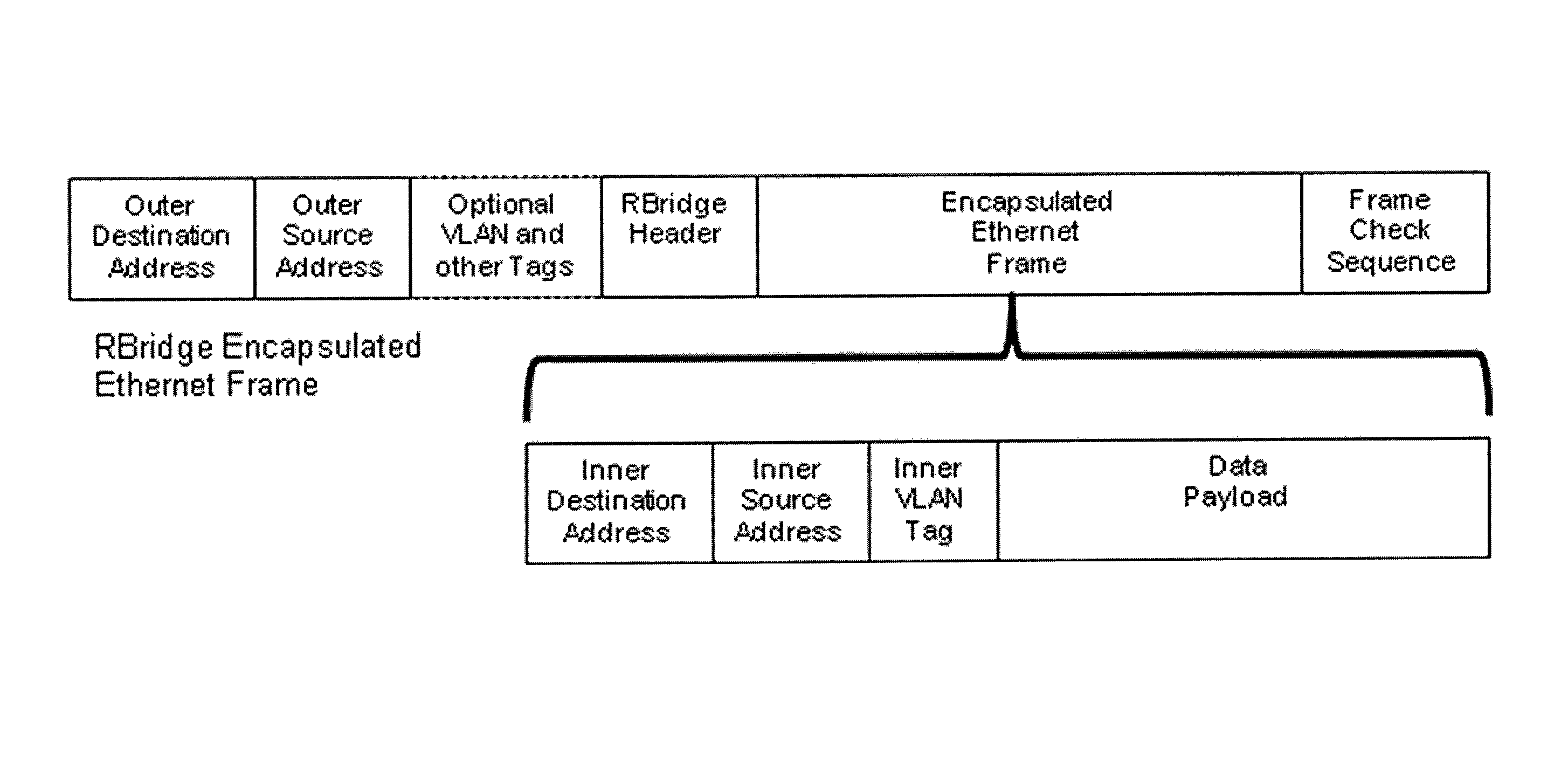
[0032]Network bandwidth is always at a premium so techniques that will make the best use of available bandwidth are valuable. There are two effects that result in wasted bandwidth: (1) Some messages sent within local networks are internally redundant, with low data density, wasting bandwidth. One example is a message whose data includes large blocks of zeros or other constant or repeating data; and (2) There is a certain amount of overhead per frame on Ethernet links and some other types of links. This overhead does not convey any useful data. It is needed to separate and identify frames, synchronize the transmission, and the like. As the average frame size gets smaller this overhead generally occupies an increasing fraction of the bandwidth on a link, since the overhead is typically a constant amount per frame. In particular, for Ethernet there is normally a seven byte preamble followed by a one byte start frame delimiter, followed by the destination and source media access address...


PUM


Abstract

Some embodiments relate to a network comprising two RBridges connected by a link where the two RBridges are not the ingress and egress RBridge for said frames, wherein said RBridges automatically exchange information as to their support of hop-by-hop reversible frame aggregation, reversible header compression, and reversible data compression, and wherein if both RBridges support any or all of these features in the same fashion, one or more of said features are automatically applied to appropriate frames at the transmitting RBridge and removed at the receiving RBridge, increasing the throughput of the link.

Description

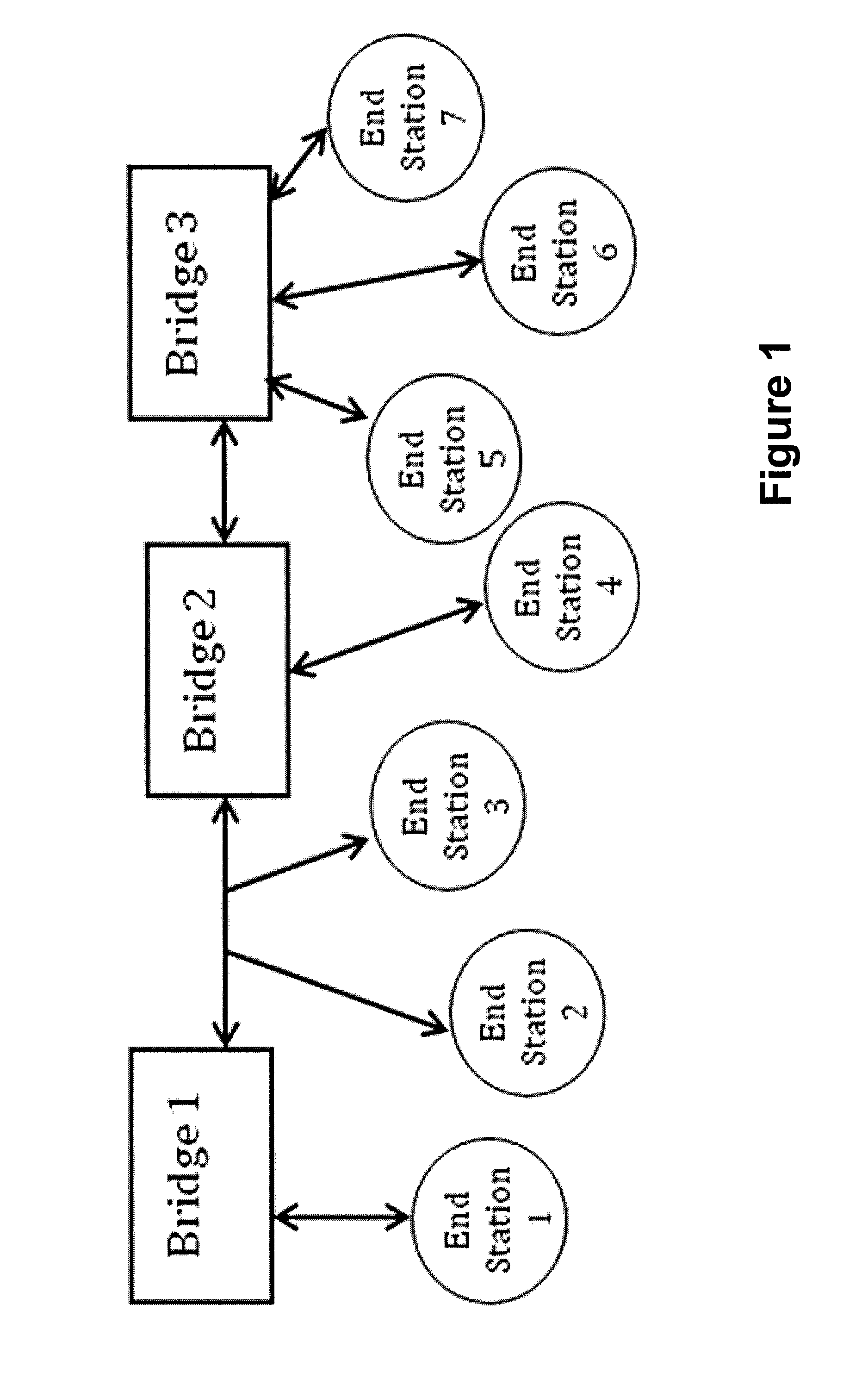
CROSS-REFERENCE TO RELATED APPLICATIONS[0001]This application claims a priority benefit, under 35 U.S.C. §119(e), of U.S. Provisional Patent Application No. 61 / 225,686, entitled “RBridge Hop-By-Hop Compression And Frame Aggregation,” filed on Jul. 15, 2009.BACKGROUND[0002]1. Field of Invention[0003]The techniques described herein are directed generally to the field of network communications between RBridges.[0004]2. Description of the Related Art[0005]Computer network bridging has great advantages. It provides a plug-and-play environment that is substantially transparent to the network data frames being sent through it. For many applications, no manual configuration of the bridges is needed. Thus in FIG. 1, end stations, such as user client or server computers or Internet Protocol routers can be attached or detached to or from various bridges or multi-access links (such as the multi-access link between Bridge 1 and Bridge 2) and, when attached, will be able to communicate with each ...

Claims


Application Information

Patent Timeline
Patent Type & Authority Patents(United States)
IPC IPC(8): H04L12/28
CPCH04L12/4625H04L47/38
Inventor EASTLAKE, III, DONALD E.
Owner EASTLAKE III DONALD E
Learn More