Scribe line forming device and scribe line forming method
a technology of forming device and forming method, which is applied in the field of forming apparatus for forming scribe lines, can solve the problems of not being able to easily form vertical cracks that have a sufficient depth in and not being able to form scribe lines by cutting the surface of the glass substrate with a point diamond
- Summary
- Abstract
- Description
- Claims
- Application Information
AI Technical Summary
Benefits of technology
Problems solved by technology
Method used
Image
Examples
first embodiment
The First Embodiment
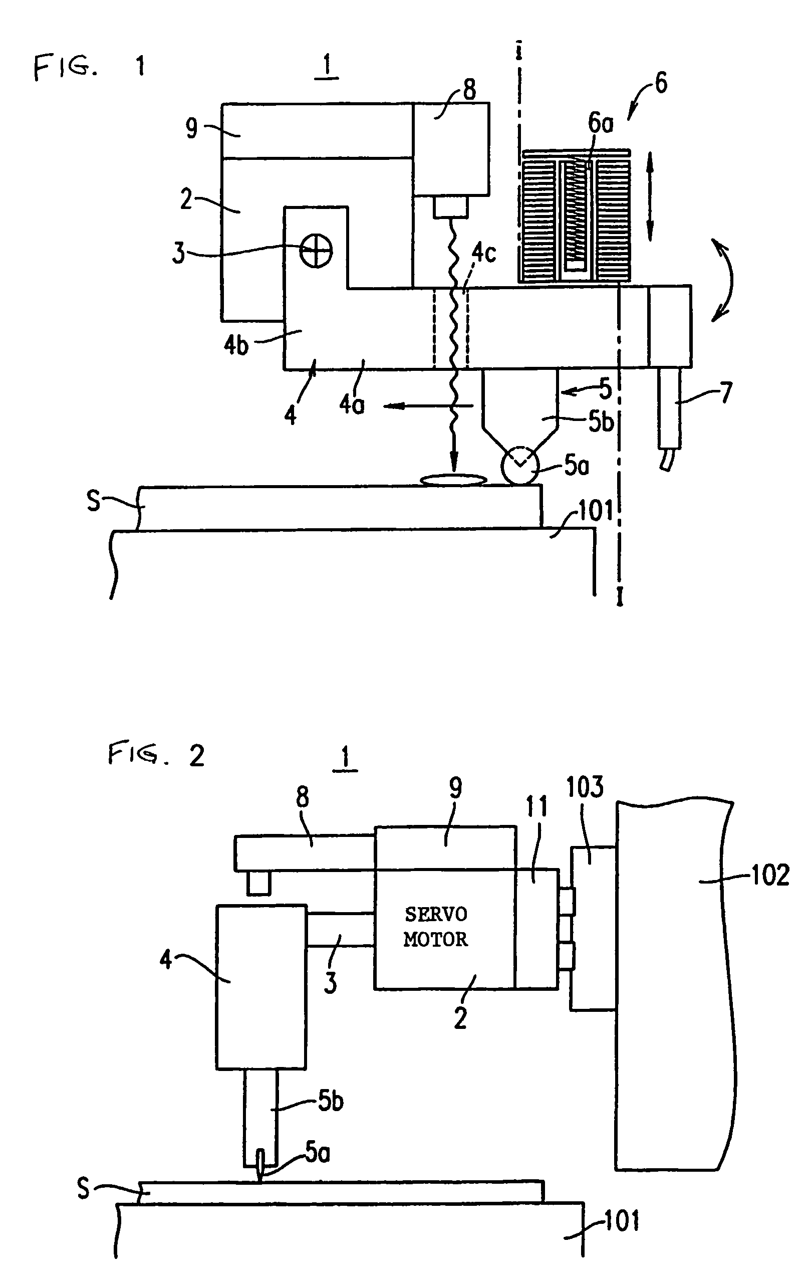
[0035]FIG. 1 is a side view that schematically shows a scribe line forming apparatus 1 according to a first embodiment. FIG. 2 is a front view of the scribe line forming apparatus 1 viewed from the I-I cross-sectional line in FIG. 1.
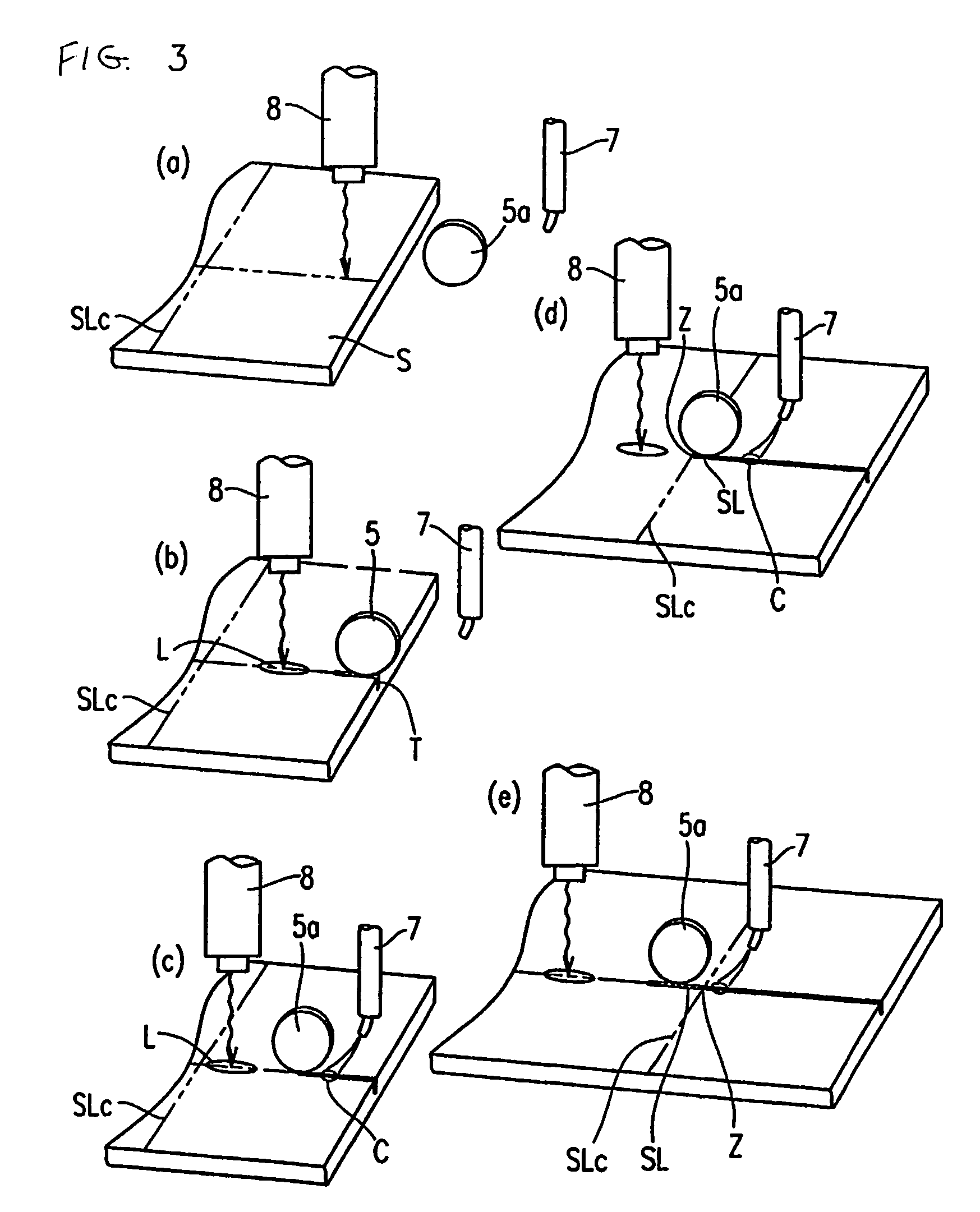
[0036]The scribe line forming apparatus 1 includes, as shown in FIGS. 1 and 2, a table 101 used for horizontally fixing a brittle material substrate S on which scribe lines are to be formed. Here, the brittle material substrate S described in the present description is, more specifically, a substrate having a large size called a mother substrate. Substrates that may be made of glass, ceramic, semiconductor wafers or the like are sequentially divided into sections of predetermined smaller sizes for a variety of uses. On a side wall 102 on the side of the table 101 used for fixing the brittle material substrate S, a guide rail 103 extending horizontally (i.e. extending in a direction vertical to the plane of the drawing page) is provide...
second embodiment
The Second Embodiment
[0067]FIG. 4 is a side view that schematically shows a scribe line forming apparatus 1′ according to the second embodiment. FIG. 5 is a front view of the scribe line forming apparatus 1′ viewed from a cross sectional line IV-IV in FIG. 4.
[0068]In the scribe line forming apparatus 1′ according to the second embodiment, as shown in FIG. 4, the laser beam oscillator 8 is provided so as to prolong toward the rear side (the right side in the drawing) from the control apparatus 9 so that a laser beam is irradiated on the rear side of the position at which the wheel tip 5a of the glass cutter 5 is in contact with the surface of the brittle material substrate S.
[0069]Since other configurations are the same as those of the scribe line forming apparatus 1 according to the first embodiment, detailed explanation will be omitted.
[0070]In the scribe line forming apparatus 1′, the wheel tip 5a, the laser beam oscillator 8, and the cooling nozzle 7 are arranged in the stated or...
third embodiment
The Third Embodiment
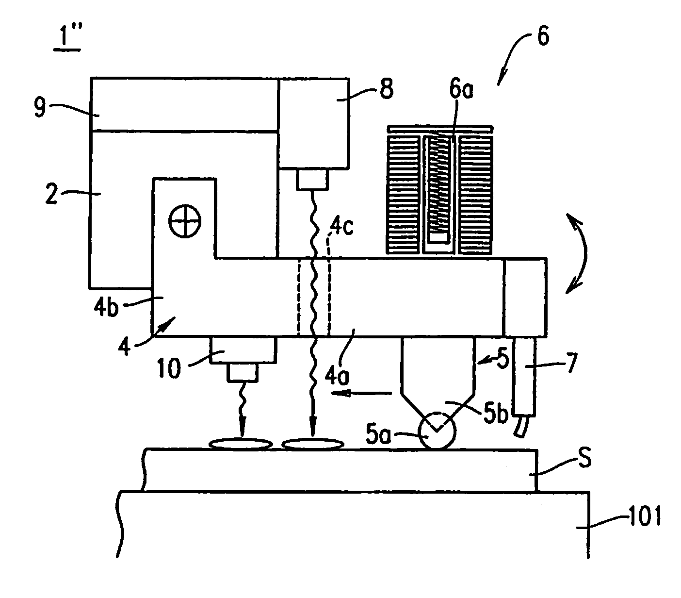
[0075]FIG. 7 is a side view that schematically shows a scribe line forming apparatus 1″ according to the third embodiment.
[0076]In the third embodiment, on the lower surface of the frame body 4a of the supporting frame 4, at a position to the fore of the glass cutter 5, a laser displacement gauge 10 is provided that detects, by irradiation of a laser beam, changes in the brittle material substrate S, such as unevenness, warps, and the like. Since other configurations are the same as those of the scribe line forming apparatus 1 according to the first embodiment, detailed explanation will be omitted.
[0077]Also, the operation of the scribe line forming apparatus 1″ of the third embodiment is substantially the same as the operation of the scribe line forming apparatus 1 according to the first embodiment described above, except that unevenness in the surface of the brittle material substrate S is detected with the use of the laser displacement gauge 10; therefore, det...
PUM
| Property | Measurement | Unit |
|---|---|---|
| pressure | aaaaa | aaaaa |
| impact force | aaaaa | aaaaa |
| depth | aaaaa | aaaaa |
Abstract
Description
Claims
Application Information
 - R&D
- Intellectual Property
- Life Sciences
- Materials
- Tech Scout
- Unparalleled Data Quality
- Higher Quality Content
- 60% Fewer Hallucinations
Browse by: Latest US Patents, China's latest patents, Technical Efficacy Thesaurus, Application Domain, Technology Topic, Popular Technical Reports.
© 2025 PatSnap. All rights reserved.Legal|Privacy policy|Modern Slavery Act Transparency Statement|Sitemap|About US| Contact US: help@patsnap.com


