
Method for calibrating a transmission line pulse test system

a technology of transmission line pulse and test system, which is applied in the direction of resistance/reactance/impedence, instruments, measurement devices, etc., can solve the problems of i waveform measurement, and achieve the effect of avoiding additional rf equipment and being easy to integra

Active Publication Date: 2012-12-25
INTERUNIVERSITAIR MICRO ELECTRONICS CENT (IMEC VZW) +1
View PDF4 Cites 0 Cited by
  • Summary
  • Abstract
  • Description
  • Claims
  • Application Information

AI Technical Summary

Benefits of technology

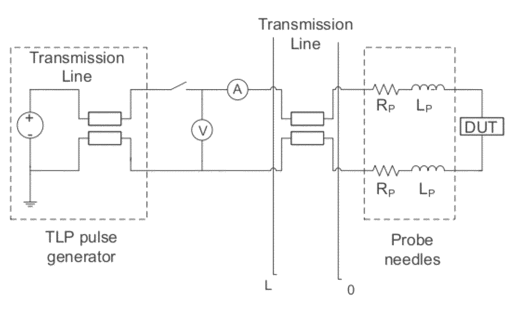
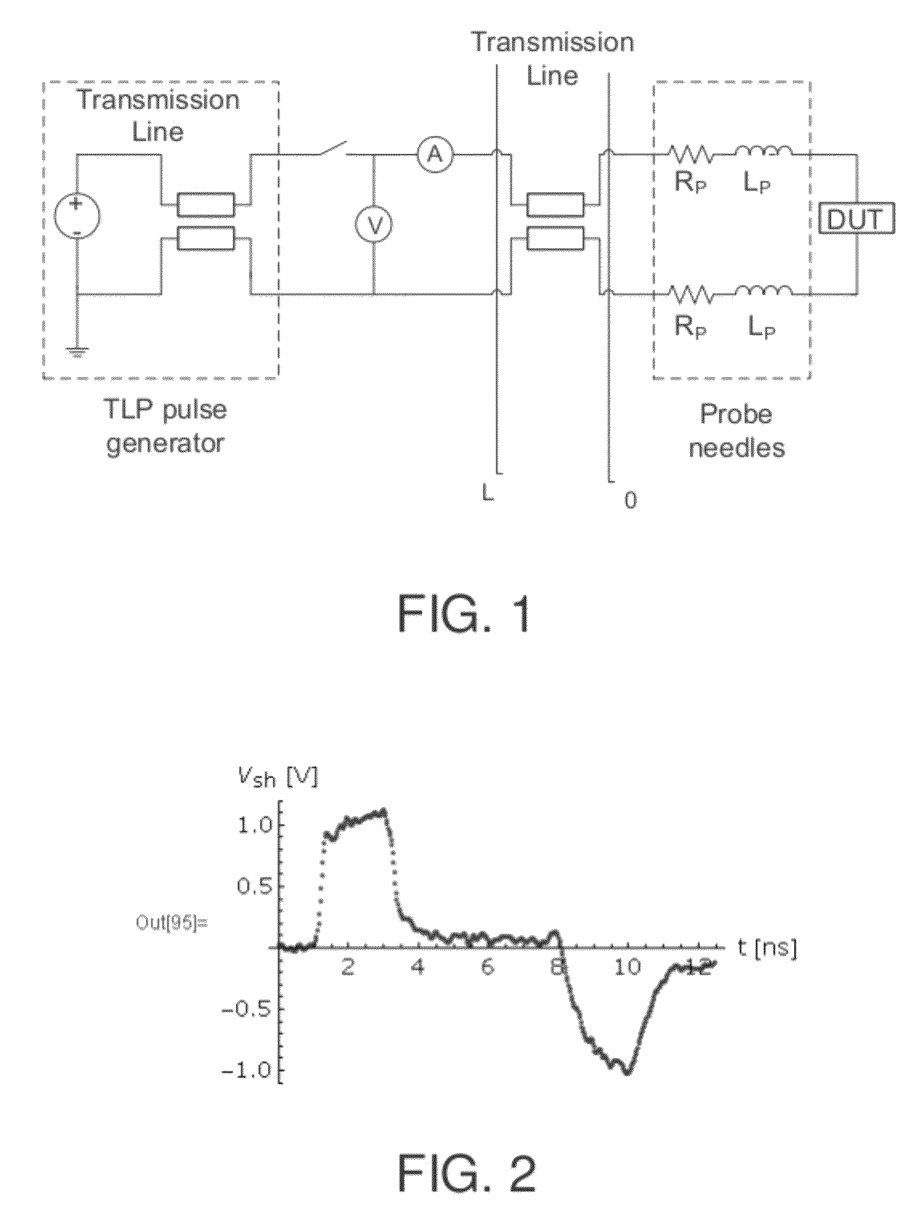
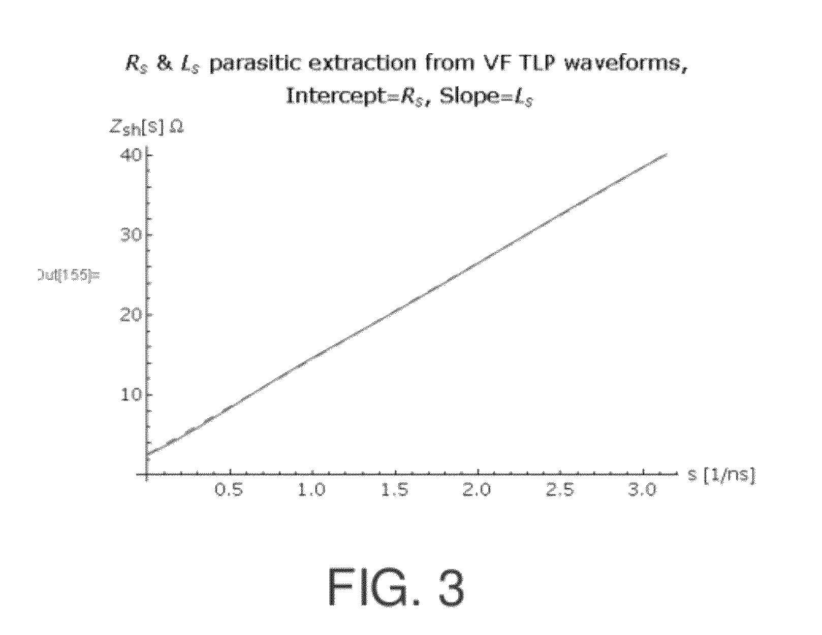
The invention provides a calibration method for a TLP test system that avoids the need for additional RF equipment. The method involves applying the test system on an open and a known calibration element, capturing voltage and current waveforms, and transforming them to the frequency domain to determine calibration data. This method can be easily integrated into existing TLP software without requiring additional hardware. The calibration is done using the voltage and current waveforms gathered on an open and a known calibration element, which allows for the extraction of a model for the needle parasitics and the lossy transmission line interconnects. The method is independent of the pulse shape generated by the tester.

Problems solved by technology

The known available measurement techniques do not result in V and I waveforms measured at the DUT level, however, as they will always include system parasitics like probe resistances and inductances, lossy transmission line interconnects etc.
This methodology needed RF characterization of the connection line and the probe parasitics, which is user unfriendly as it requires additional costly RF test equipment.

Method used


Image

  • Method for calibrating a transmission line pulse test system
  • Method for calibrating a transmission line pulse test system
  • Method for calibrating a transmission line pulse test system

Examples


Embodiment Construction

[0028]The present invention will be described with respect to particular embodiments and with reference to certain drawings but the invention is not limited thereto but only by the claims. The drawings described are only schematic and are non-limiting. In the drawings, the size of some of the elements may be exaggerated and not drawn on scale for illustrative purposes. The dimensions and the relative dimensions do not necessarily correspond to actual reductions to practice of the invention.

[0029]Furthermore, the terms first, second, third and the like in the description and in the claims, are used for distinguishing between similar elements and not necessarily for describing a sequential or chronological order. The terms are interchangeable under appropriate circumstances and the embodiments of the invention can operate in other sequences than described or illustrated herein.

[0030]Moreover, the terms top, bottom, over, under and the like in the description and the claims are used fo...


PUM


Abstract

Calibration method for calibrating transient behavior of a TLP test system. The system comprises a TLP generator, probe needles, nominally impedance matched transmission lines and measurement equipment, connected between the transmission lines and the TLP generator, for detecting transient behavior of a device under test by simultaneously capturing voltage and current waveforms as a result of generated pulses. The calibration method comprises (a) applying the TLP test system on an open and capturing first voltage and current waveforms; (b) applying the TLP test system on a calibration element having a known finite impedance and a known transient response and capturing second voltage and current waveforms; (c) transforming the captured first and second current and voltage waveforms to the frequency domain, and (d) determining calibration data for the transient behavior of the TLP test system on the basis of the transformed first and second voltage and current waveforms.

Description

CROSS-REFERENCE TO RELATED APPLICATION[0001]The present application claims priority to European Patent Application EP08172843.8 filed in the European Patent Office on Dec. 23, 2008, the entire contents of which is incorporated herein by reference.BACKGROUND[0002]1. Technical Field[0003]The present invention relates to a method for calibrating a transmission line pulse (TLP) test system.[0004]2. Background Art[0005]Different on-wafer ESD test equipments are available today: TLP, vfTLP, HBM, and MM ESD tests. During such ESD stress tests, one wants to characterize the voltage and current waveforms through the device under test (DUT), during such an ESD stress. The known available measurement techniques do not result in V and I waveforms measured at the DUT level, however, as they will always include system parasitics like probe resistances and inductances, lossy transmission line interconnects etc.[0006]Consequently, TLP type of measurements are only used for quasi static characteriza...

Claims


Application Information

Patent Timeline
Patent Type & Authority Patents(United States)
IPC IPC(8): G01R27/02
CPCG01R35/005G01R31/002G01R31/021G01R31/58
Inventor ROUSSEL, PHILIPPELINTEN, DIMITRI
Owner INTERUNIVERSITAIR MICRO ELECTRONICS CENT (IMEC VZW)
Learn More