Heat sink cooling arrangement for multiple power electronic circuits

a technology of electronic circuits and heat sinks, applied in the direction of lighting, heating apparatus, electric apparatus casings/cabinets/drawers, etc., can solve the problems of reducing reliability, increasing failure rates, and increasing the need for efficient heat dissipation

Inactive Publication Date: 2012-12-18
ROCKWELL AUTOMATION TECH
View PDF46 Cites 27 Cited by
  • Summary
  • Abstract
  • Description
  • Claims
  • Application Information

AI Technical Summary

Problems solved by technology

Therefore, as packaged control units become more compact, the need for efficient heat dissipation becomes more critical.
Additionally, as the workload or motor speed changes, the temperature of the semiconductors generally increases, causing higher failure rates and reduced reliability.
The output of the unit is often, therefore, limited by the maximum temperature that the unit can handle without substantially increasing the risk of failure.

Method used


Image

  • Heat sink cooling arrangement for multiple power electronic circuits
  • Heat sink cooling arrangement for multiple power electronic circuits
  • Heat sink cooling arrangement for multiple power electronic circuits

Examples


Embodiment Construction

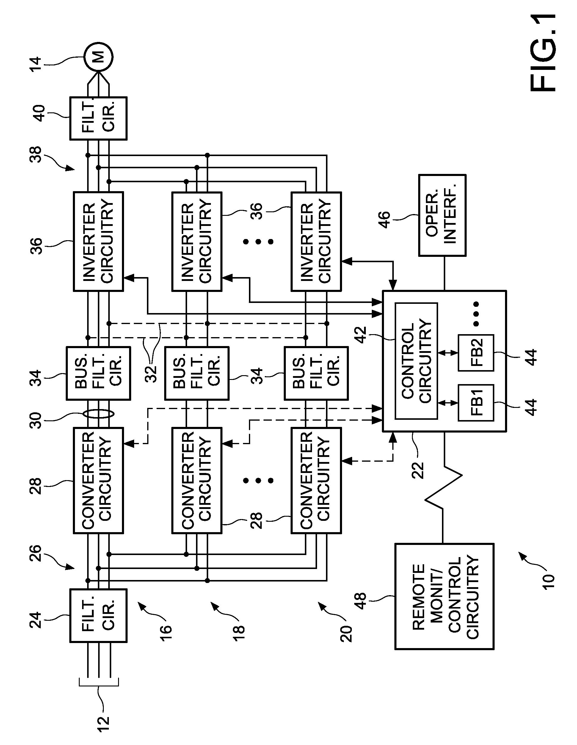
[0023]Turning now to the drawings, FIG. 1 represents a drive system 10 in accordance with aspects of the present disclosure. The drive system 10 is configured to be coupled to a source of AC power, such as the power grid, as indicated by reference numeral 12, and to deliver conditioned power to a motor 14 or any other suitable load. The system 10 comprises a plurality of individual drives coupled to one another in parallel to provide power to the load. In the example illustrated in FIG. 1, for example, a first drive 16 is illustrated as coupled to a second drive 18 and a further drive 20 which may be the third, fourth, fifth, or any suitable terminally numbered drive. A presently contemplated embodiment may accommodate up to five parallel drives, although fewer or more may be configured in the same way. It should be noted that certain aspects of the techniques described herein may be used with a single drive. However, other aspects are particularly well-suited for multiple parallel ...


PUM

PropertyMeasurementUnit
acute angleaaaaaaaaaa
angleaaaaaaaaaa
angleaaaaaaaaaa

Abstract

The present invention relates generally to tuning the flow of cooling air across converter and inverter heat sinks in a motor drive system. More specifically, present techniques relate to motor drive duct systems including heat sinks with separate, sequential heat sink fin sections disposed in a common cooling air path and having different geometries to optimize the flow of cooling air across and between fins of the separate heat sink fin sections. For example, the heat sink fin sections may have different fin lengths, fin heights, fin counts, fin pitch (e.g., distance between adjacent fins), and so forth. Each of these different geometric characteristics may be tuned to ensure that temperatures and temperature gradients across the heat sinks are maintained within acceptable ranges.

Description

BACKGROUND[0001]The present invention relates generally to the field of power electronic devices such as those used in power conversion or applying power to motors and similar loads. More particularly, the invention relates to optimizing the flow of cooling air across motor drive heat sinks.[0002]In the field of power electronic devices, a wide range of circuitry is known and currently available for converting, producing, and applying power to loads. Depending upon the application, such circuitry may convert incoming power from one form to another as needed by the load. In a typical arrangement, for example, constant (or varying) frequency alternating current power (such as from a utility grid or generator) is converted to controlled frequency alternating current power to drive motors, and other loads. In this type of application, the frequency of the output power can be regulated to control the speed of the motor or other device. Many other applications exist, however, for power el...

Claims


Application Information

Patent Timeline
Patent Type & Authority Patents(United States)
IPC IPC(8): H05K7/20
CPCH05K7/20163H05K7/20909H05K13/0023H05K7/209Y10T29/49002H05K13/00
Inventor WEISS, BRUCE W.
Owner ROCKWELL AUTOMATION TECH
Why Eureka
Try Eureka