
Power amplifier linearization using digital predistortion

a technology of power amplifiers and linearization, applied in amplifiers, transmission monitoring, electrical devices, etc., to achieve the effect of avoiding distortion in output signals, maintaining transmit (tx) power, and increasing signal amplitud

Inactive Publication Date: 2012-12-04
QUALCOMM INC
View PDF23 Cites 21 Cited by
  • Summary
  • Abstract
  • Description
  • Claims
  • Application Information

AI Technical Summary

Benefits of technology

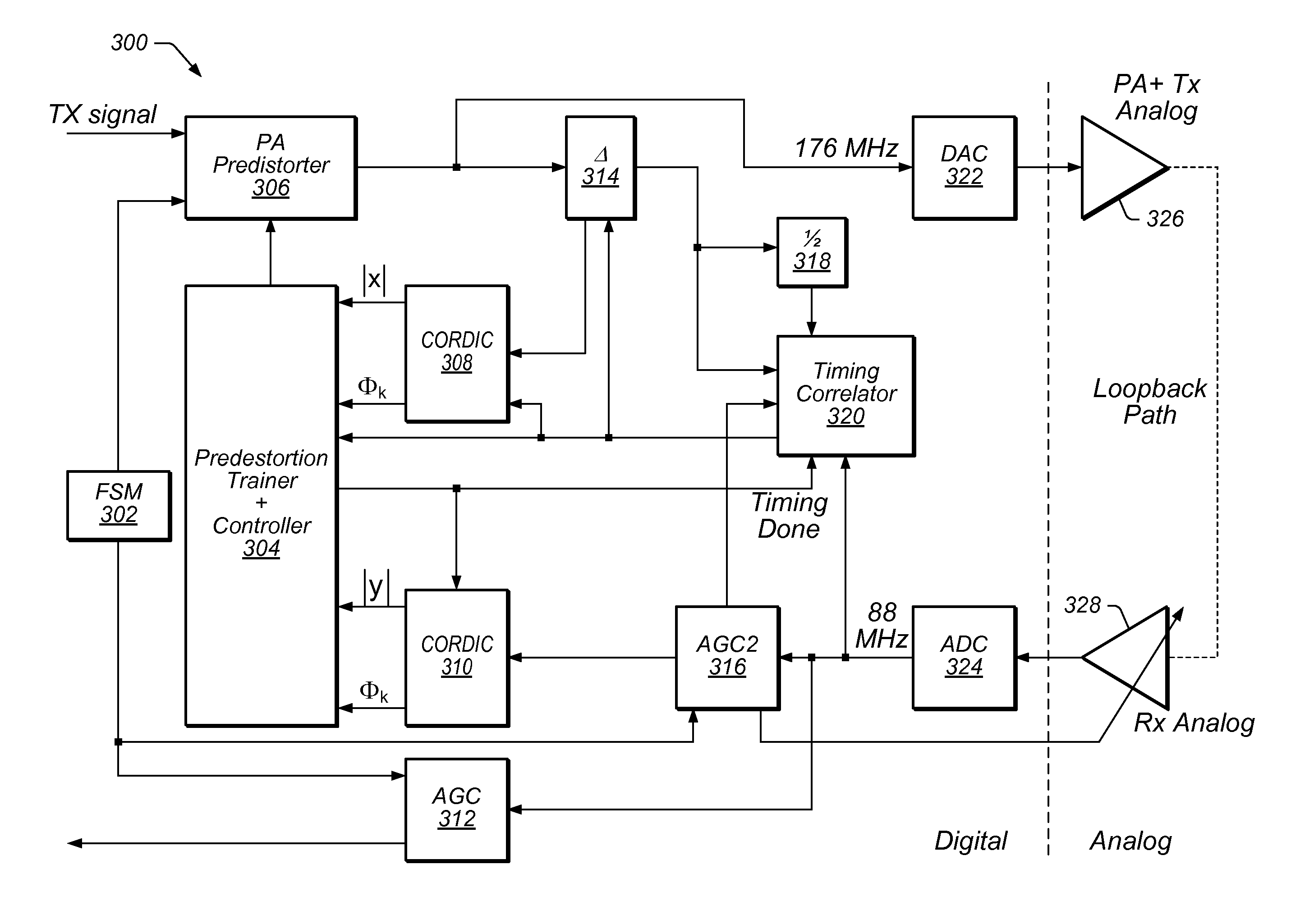
[0009]In one set of embodiments, predistortion may be employed to avoid distortion in the output signal of a transmitter, more specifically in the output signal of a power amplifier (PA) at the end of the transmitter path, while at least maintaining transmit (TX) power. In some cases, predistortion may actually operate to increase the output power to a certain extent, since it may uncompress higher signal amplitudes. An active transmission signal, instead of test tones, may be used for training a predistorter for the power amplifier (PA) and the entire analog transmit path of the transmitter (the transmit path may also be the transmit path of a transmitter / receiver, i.e. transceiver), via a loopback path from the output of the transmitter path to the input of a receiver path. The transmitter path may include an upconverter of the transmitter, and the receive path may include a downconverter. The transfer function of the PA may be estimated as a polynomial function, obtaining the coefficients of the polynomial function using adaptation techniques according to one of a number of possible different methods. In one set of embodiments, the coefficients of the polynomial function may be obtained through curve fitting using a least mean square (LMS) algorithm.
[0010]The predistortion coefficients, thereby obtained, may then be used for performing predistortion to correct for potential non-linearities in the PA output due to the inherent non-linearities of the PA. By using a feedback loop that includes both the upconverter and the downconverter using a same oscillator, phase noise added by the upconverter may be cancelled by the downconverter. Consequently, there may be no need to use separate paths for incorporating the upconverter and downconverter. The predistortion training and operation may also incorporate fractional timing correction, to properly align the received version of the original TX signal with the original TX signal. Effectively time aligning the input and output of the PA (which is in the transmit path of the transmitter) may allow for accurate evaluation of the PA transfer function. Therefore, the loopback path may be used to eliminate phase error (noise), and the fine timing alignment provided by the fractional timing correction may ensure further accuracy of the PA output signal or the accuracy of the PA transfer function.

Problems solved by technology

In some cases, predistortion may actually operate to increase the output power to a certain extent, since it may uncompress higher signal amplitudes.

Method used


Image

  • Power amplifier linearization using digital predistortion
  • Power amplifier linearization using digital predistortion
  • Power amplifier linearization using digital predistortion

Examples


Embodiment Construction

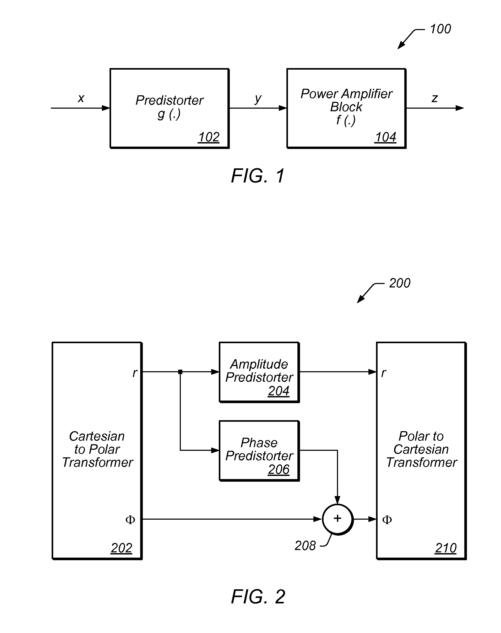
[0021]Various embodiments of a transmitter or transceiver that use a power amplifier (PA) for signal transmission may include a predistortion circuit (predistorter) for predistorting the signal to be transmitted prior to the digital-to-analog conversion, in order to compensate for potential non-linearities in the PA output. A non-linearity may manifest itself in an amplifier as an amplitude-dependent gain. That is, the gain of the amplifier may be typically lower for higher amplitude signals than for lower amplitude signals. This is commonly referred to as amplitude distortion. To compensate for amplitude distortion, a predistorter (e.g. in FIG. 1) may be configured to pre-emphasize / amplify higher amplitude signals to ensure that the overall gain—of the predistorter stage and the amplifier stage as a whole—remains the same regardless of the amplitude of the input. In addition to amplitude distortion, the amplifier's output may be also affected by phase distortion. The phase distorti...


PUM


Abstract

Predistortion may be employed to avoid distortion in the output of a power amplifier (PA) in a transmitter, while maintaining transmit power. An active transmission signal, instead of test tones, may be used for training a predistorter for the PA, and for the entire analog transmit path of the transmitter, via a loopback path from the output of the PA to the input of a receiver path. The transmitter may include an upconverter, and the receive path may include a downconverter, which may therefore both be included in the loopback path, helping eliminate phase noise. The predistortion training may incorporate fractional timing correction, to properly align the amplified version of the original TX signal received via the loopback path with the original TX signal. The transfer function of the PA may be estimated as a polynomial function, obtaining the coefficients of the polynomial function using adaptation techniques according to one of a number of possible different methods, e.g. through curve fitting using a least mean square (LMS) algorithm.

Description

BACKGROUND OF THE INVENTION[0001]1. Field of the Invention[0002]This invention relates to amplifier design, and, more particularly, to the design of Power Amplifiers.[0003]2. Description of the Related Art[0004]Electronic amplifiers are used for increasing the power and / or amplitude of various specified signals. Most amplifiers operate by sinking current from a power supply, and controlling the output signal to match the shape of the input signal, but having a higher amplitude. Amplifiers are typically specified according to their input and output characteristics. One of the main characteristics of an amplifier is its gain, which relates the magnitude of the output signal to the magnitude of the input signal. The gain may be specified as the ratio of the output voltage and the input voltage, or the ratio of the output power and the input power. The gain relationship is oftentimes expressed as the transfer function of the amplifier. In most cases, the transfer function of an amplifie...

Claims


Application Information

Patent Timeline
IPC IPC(8): H04B1/04
CPCH04B1/0475H04B2001/0425H03F1/3241
Inventor PEIRIS, BEMINI HENNADIGE JANATHSANKARAN, SUNDAR G.
Owner QUALCOMM INC
Learn More