
A signal transmission method, system and device

A signal transmission and signal technology, applied in the field of communication, can solve the problems of reducing signal PAPR, RF power amplifier output signal distortion, etc., to achieve the effect of avoiding signal distortion and reducing PAPR

Active Publication Date: 2021-02-12
HUAWEI TECH CO LTD
View PDF6 Cites 0 Cited by
  • Summary
  • Abstract
  • Description
  • Claims
  • Application Information

AI Technical Summary

Problems solved by technology

[0004] The present application provides a signal transmission method, system and device for reducing the PAPR of the signal and solving the problem that the high PAPR of the signal easily leads to the distortion of the output signal of the radio frequency power amplifier

Method used


Image

  • A signal transmission method, system and device
  • A signal transmission method, system and device
  • A signal transmission method, system and device

Examples


Embodiment Construction

[0136] Embodiments of the present application are described below in conjunction with the accompanying drawings.

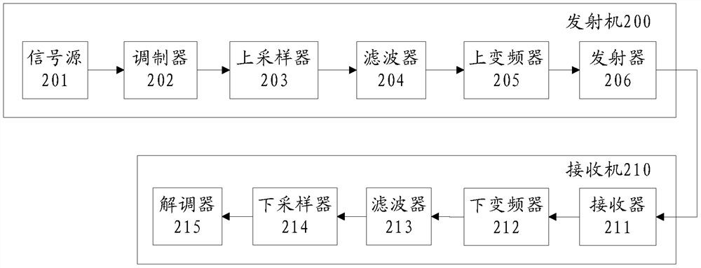
[0137] In the traditional wireless signal transmission system, the input signal power is mainly amplified by the radio frequency power amplifier to a level suitable for wireless channel transmission. for example figure 2 A schematic structural diagram of a traditional wireless signal transmission system is shown.

[0138] Such as figure 2 As shown, in the traditional transmitter 200, after the baseband signal sent by the signal source 201 is modulated by the modulator 202, it is interpolated to the required working clock by the upsampler 203, filtered by the filter 204, and the signal is converted by the upconverter 205 After moving to the intermediate frequency, the transmitter 206 modulates the signal to an applicable frequency band and amplifies the signal to a suitable power, and then transmits it to the receiver 210 . Devices in the transmitter 206 inclu...


PUM


Abstract

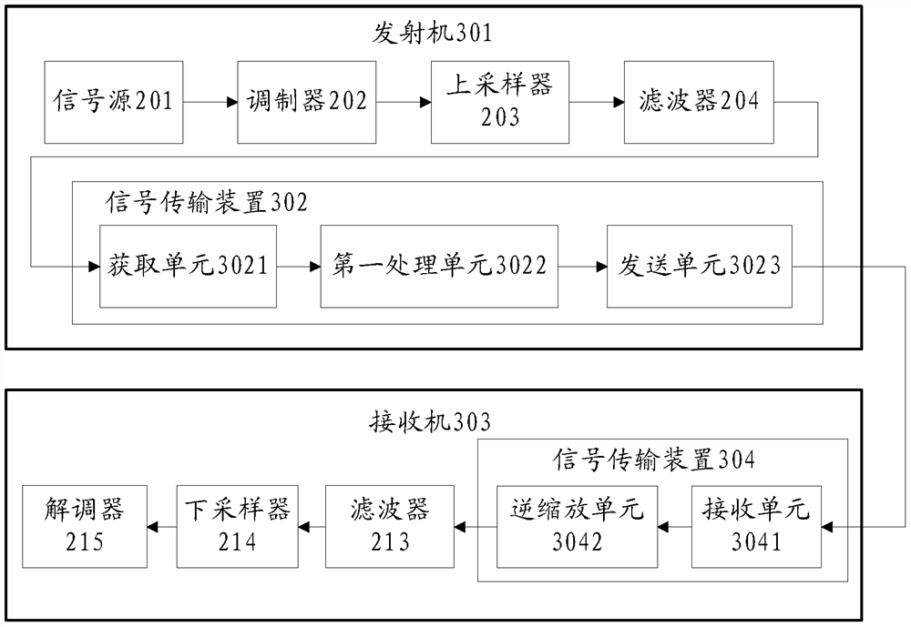
The application discloses a signal transmission method, system and device. The method of the present application includes: the transmitter acquires a signal segment of a set length to be transmitted; the transmitter calculates the scaling factor corresponding to the signal segment according to the power of the signal in the acquired signal segment, and uses the scaling factor corresponding to the signal segment The coefficient scales the amplitude of the signal in the signal segment; the transmitter sends the scaling coefficient corresponding to the signal segment and the scaled signal segment to the receiver. The present application can reduce the PAPR of the signal, and solve the problem that the high PAPR of the signal easily leads to distortion of the output signal of the radio frequency power amplifier.

Description

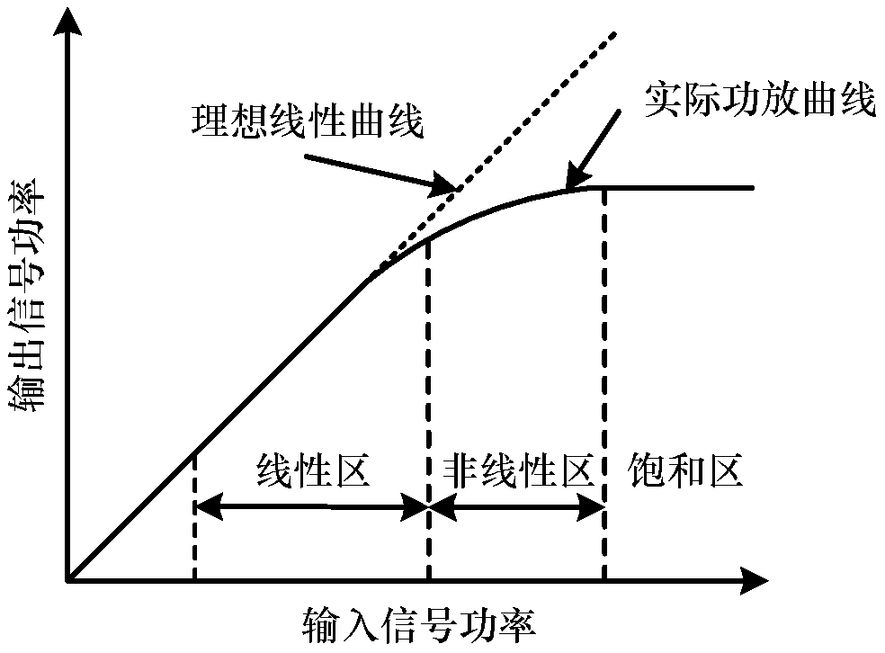
technical field [0001] The present application relates to the field of communication technologies, and in particular to a signal transmission method, system and device. Background technique [0002] RF power amplifier is an important part of wireless communication system, it amplifies the input signal power to a level suitable for wireless channel transmission. The efficiency of RF power amplifiers affects the stability of communication systems. However, the RF power amplifier is not a linear device. When the input signal power reaches a certain level, the output power of the RF power amplifier does not output according to the original linear characteristic, but is lower than the original linear characteristic output power. figure 1 The characteristic curve of the RF power amplifier is shown. When the input signal amplitude reaches a certain level, the RF power amplifier enters the nonlinear region and saturation region from the linear region, which will cause problems such...

Claims


Application Information

Patent Timeline
Patent Type & Authority Patents(China)
IPC IPC(8): H04W52/06
CPCH04W52/06
Inventor 李良李泓孙德福代秀琼罗锐
Owner HUAWEI TECH CO LTD
Learn More