
Spatially controlled atomic layer deposition in porous materials

a technology of porous materials and atomic layers, which is applied in the direction of catalyst activation/preparation, physical/chemical process catalysts, coatings, etc., can solve the problems of limited technique to deposited mask patterns on flat surfaces, and limited technique to planar substrates

Active Publication Date: 2012-11-27
UCHICAGO ARGONNE LLC
View PDF1 Cites 8 Cited by
  • Summary
  • Abstract
  • Description
  • Claims
  • Application Information

AI Technical Summary

Benefits of technology

The present invention provides methods for selectively depositing materials on complex geometries within a porous substrate using ALD techniques. These methods involve masking the substrate with a masking precursor to prevent adsorption of subsequently applied metal precursors. The masking precursor reacts with the substrate to form a metal precursor, which coats an unmasked portion of the pore surface. The metal precursor reacts with and coats an unmasked pore surface. The depth of the coating is controllable by regulating exposure of the substrate to the masking precursor. The methods can be used to deposit various metal oxides, metals, metal nitrides, metal sulfides, metal phosphides, metal carbides, and other ALD materials. The methods have applications in a variety of fields such as synthesizing nano-porous catalytic membranes, catalysts, sensors, separations membranes, electron multipliers, solar cells, and nuclear fuel assemblies.

Problems solved by technology

Although a variety of techniques have been developed to allow patterning of ALD films using masking or passivating agents, these techniques are limited to planar substrates.
However, such techniques are limited to depositing a mask pattern on a flat surface.

Method used


Image

  • Spatially controlled atomic layer deposition in porous materials
  • Spatially controlled atomic layer deposition in porous materials
  • Spatially controlled atomic layer deposition in porous materials

Examples


example 1

Preparation of AAO Membrane Samples

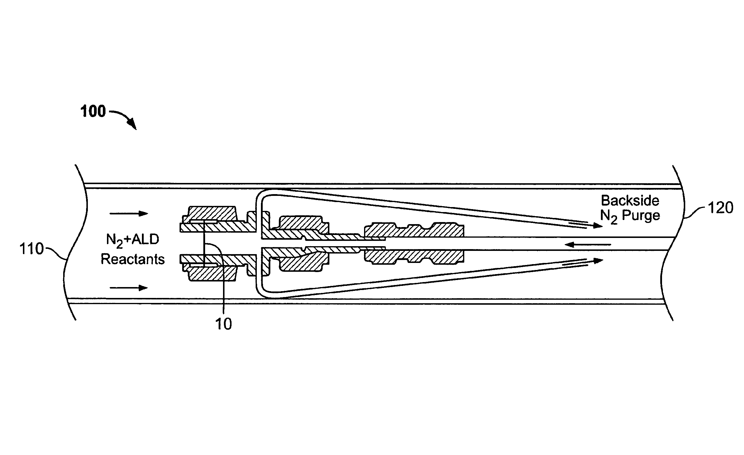
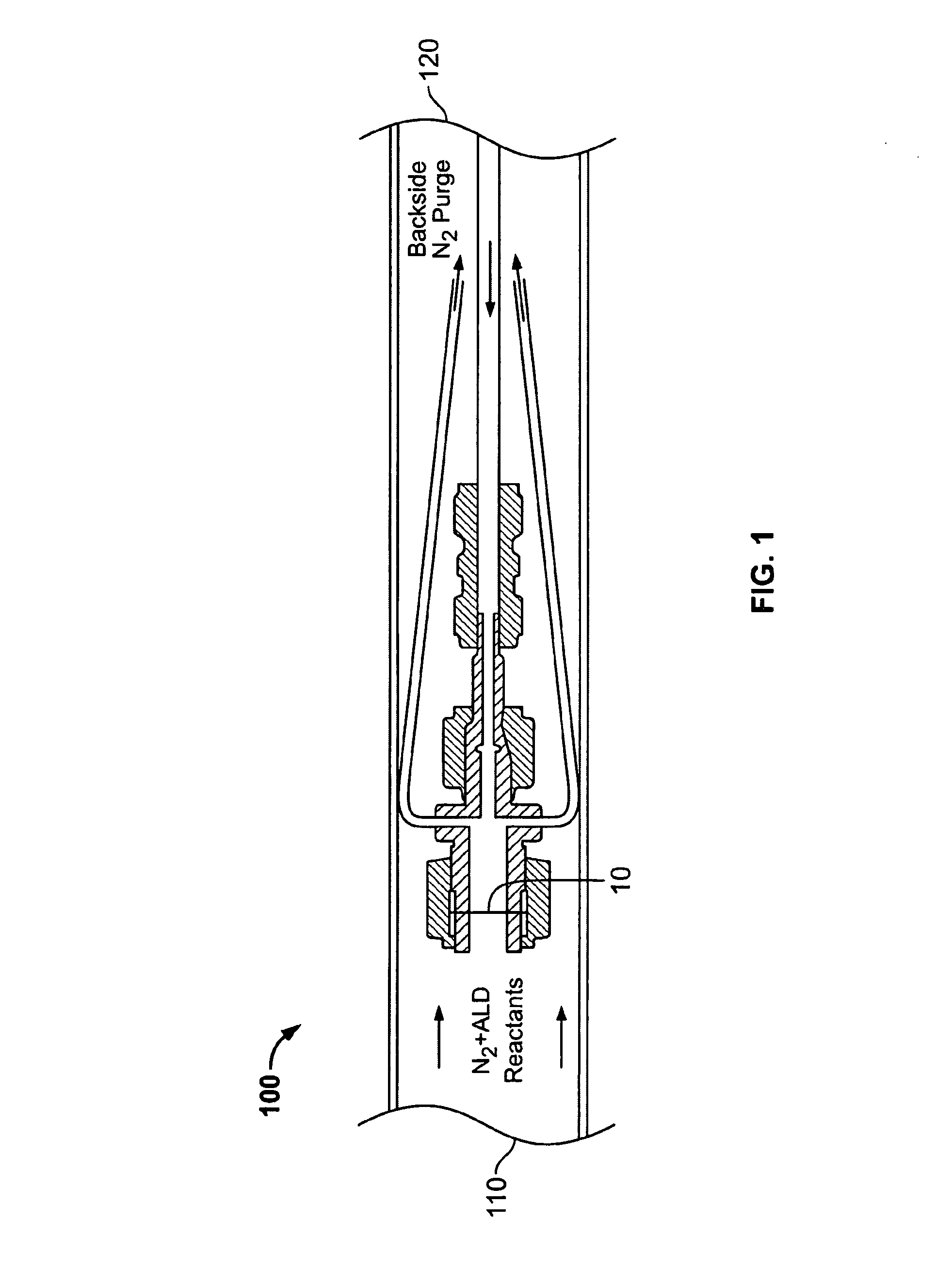
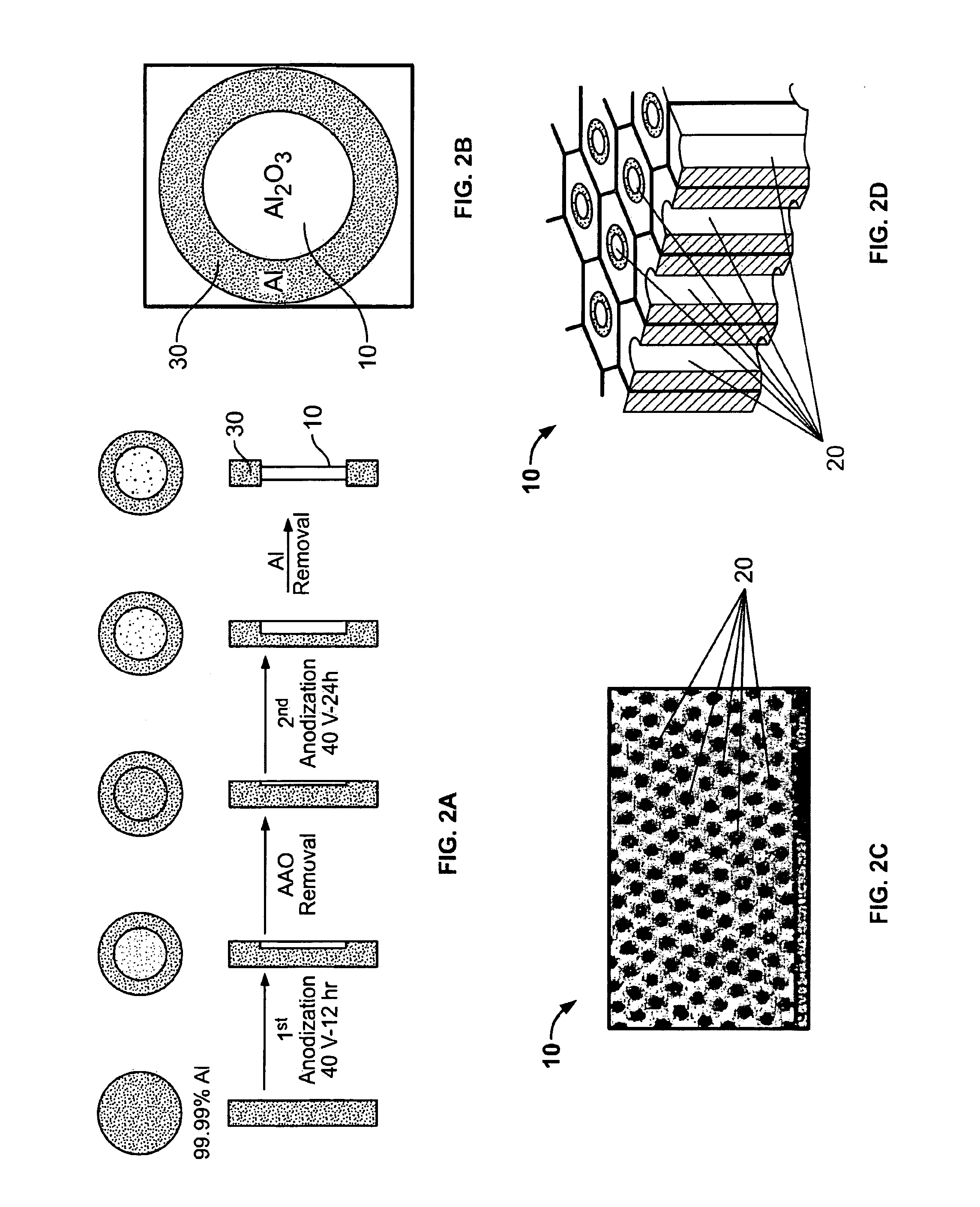
[0036]The AAO membranes 10 were prepared by the electrochemical anodization of high purity aluminum metal disks. The disks had a thickness of 0.6 mm and a diameter of 19 mm. A two-step anodization procedure was performed in 0.3 M oxalic acid at 40 V to obtain well-ordered pore arrays in the disks. Boundary layer removal was accomplished using phosphoric acid. As illustrated in FIG. 2A, a masking process employed during the anodization and boundary layer removal steps allowed a free-standing AAO membrane to be fabricated, attached about its perimeter to the starting thickness of aluminum. A gas-tight seal in the viscous flow reactor 100 was applied to the resulting samples using commercial VCR® face-seal fittings. The resulting AAO membranes 10, depicted in FIG. 2B, were 10 mm in diameter and had a thickness of about 70 μm to 75 μm. Analysis of the AAO membranes 10, using scanning electron microscopy (“SEM”), revealed an average pore diameter of 56 ...

example 2

Monte Carlo Simulation

[0038]Monte Carlo simulations were performed to evaluate the EDAX measurements obtained from the AAO membranes. These simulations modeled the AAO pores as a one-dimensional array, and simulated the ALD stripe-coating experiments by following the trajectories of individual TMA and DEZ molecules diffusing along the nanopores. Knudsen diffusion was assumed because the mean free path of the DEZ molecules in 1 Torr N2, about 50 μm, is much greater than the AAO pore diameter, about 50 nm. Consequently, the diffusion was simulated as a one-dimensional random walk of hop-length D, the local pore diameter. After each hop, if the molecule encountered an empty site, the molecule would react with probability equal to the reactive sticking coefficient, 10−3. Each trajectory continued until the molecule reacted or left the tube, and the number of trajectories was selected to model the experimental exposure times and the pressures of DEZ and TMA, respectively. The H2O exposur...

example 3

Formation of ZnO Surface Stripes in AAO

[0039]A stripe of ZnO was formed at the surface edge of the AAO membrane 10 by applying 60 cycles of DEZ / H2O with the timing sequence 1-10-1-10. The results achieved by this process are illustrated in FIGS. 5A, 5B and 5C. The DEZ and H2O exposure times were chosen to be sub-saturating so that the precursors would not completely infiltrate the nanopores. Following the deposition, the AAO membrane 10 was cleaved, and a cross-sectional specimen was analyzed by SEM and EDAX. FIG. 5A shows a SEM secondary electron image of the sample. The location of the back side of the membrane is indicated by the interface between the silver epoxy and the AAO membrane 10. FIG. 5B shows an EDAX map of the distribution of Zn in the sample as monitored by the Zn Lα line. The z-axis in FIG. 5B is aligned substantially parallel to the AAO pores. The Zn penetrates approximately 8 microns into the AAO membrane 10 as shown in FIG. 5B.

[0040]FIG. 5C shows a linescan of the...


PUM

PropertyMeasurementUnit
aspect ratioaaaaaaaaaa
pressureaaaaaaaaaa
diameteraaaaaaaaaa

Abstract

Methods for the selective deposition of materials within a porous substrate. The methods use the passivating effects of masking precursors applied to the porous substrate. A portion of a pore surface within the substrate is masked by exposing the substrate to one or more masking precursors. The depth of the pore surface that is masked is controllable by regulating the exposure of the substrate to the masking precursor. Application of the masking precursor prevents adsorption of one or more subsequently applied metal precursors about a portion of the pore surface coated by the masking precursor. Less than an entirety of the unmasked pore surface is coated by the metal precursor, forming a metal stripe on a portion of the pore surface. The depth of the metal stripe is controllable by regulating exposure of the porous substrate to the metal precursor. Subsequent exposure of the substrate to a saturating water application oxidizes the deposited precursors.

Description

CROSS REFERENCE TO RELATED PATENT APPLICATIONS[0001]The present application claims priority to U.S. Provisional Patent Application No. 61 / 060,025, filed Jun. 9, 2008 incorporated herein by reference in its entirety.STATEMENT OF GOVERNMENT INTEREST[0002]The United States Government claims certain rights in this invention pursuant to Contract No. W-31-109-ENG-38 between the United States Government and the University of Chicago and / or pursuant to DE-AC02-06CH11357 between the United States Government and UChicago Argonne, LLC representing Argonne National Laboratory.FIELD OF THE INVENTION[0003]This invention is directed toward methods for depositing materials within porous substrates employing atomic layer deposition (“ALD”) techniques. More particularly, the invention is directed toward methods of ALD for depositing uniform films at controlled depths and widths within the pores of various porous substrates through application of passivating precursors.BACKGROUND OF THE INVENTION[0004...

Claims


Application Information

Patent Timeline
Patent Type & Authority Patents(United States)
IPC IPC(8): C23C16/00
CPCB01J35/065B01J37/0226C23C16/042C23C16/045C23C16/403C23C16/405C23C16/407C23C16/45525C23C16/45555B01J35/59
Inventor ELAM, JEFFREY W.LIBERA, JOSEPH A.PELLIN, MICHAEL J.STAIR, PETER C.
Owner UCHICAGO ARGONNE LLC
Learn More