
Audio system

a technology of audio system and control system, applied in the field of audio system, can solve the problems the troublesome volume control, and the conventional audio system having a problem of increasing the load of the control system at the volume control, so as to achieve the effect of carrying out volume control (gain adjustment) very easily

Inactive Publication Date: 2012-10-23
MITSUBISHI ELECTRIC CORP
View PDF16 Cites 0 Cited by
  • Summary
  • Abstract
  • Description
  • Claims
  • Application Information

AI Technical Summary

Benefits of technology

The present invention is an audio system that includes multiple audio sources for outputting different audio signals. The system includes gain adjusting means for adjusting the gain of an audio signal from each source and outputting it. The system also includes memory means for storing gains to be set in the gain adjusting means for each audio source. When the system is selected, it automatically adjusts the gain to match the selected audio source, making it easy for users to control the volume. The technical effect of this invention is to provide a convenient and easy way for users to adjust the volume of different audio sources.

Problems solved by technology

In other words, since the volume level varies in accordance with the audio source, the user must perform the volume control every time the audio source is selected, and the volume control is usually troublesome.
Therefore the conventional audio systems have a problem of not only increasing the load in the control system at the volume control, but also of being very troublesome when the number of the audio sources is large because the user must set their volume levels in advance.
However, the conventional audio systems have a problem of increasing the load of the control system at the volume control because they must successively compare the signal level detected by the signal level detecting means with the signal level read from the memory means.

Method used


Image

  • Audio system
  • Audio system
  • Audio system

Examples


embodiment 1

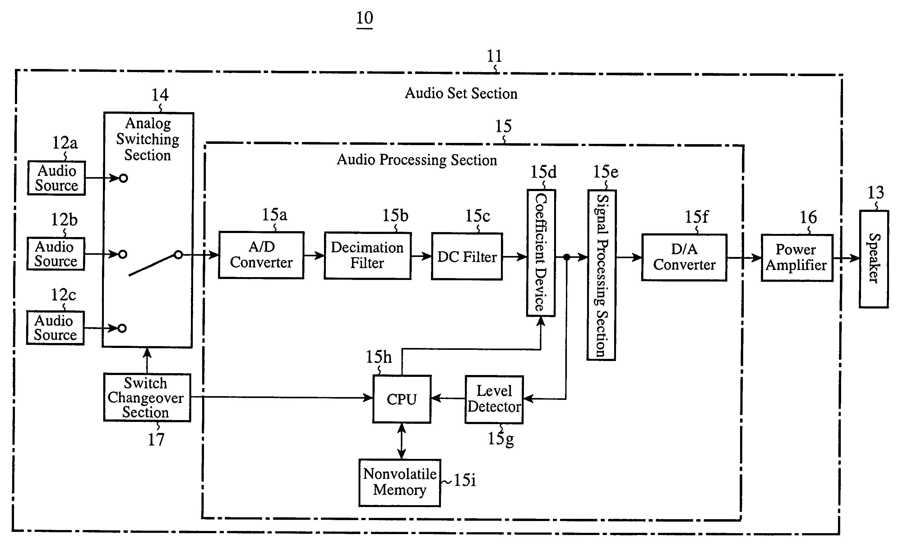
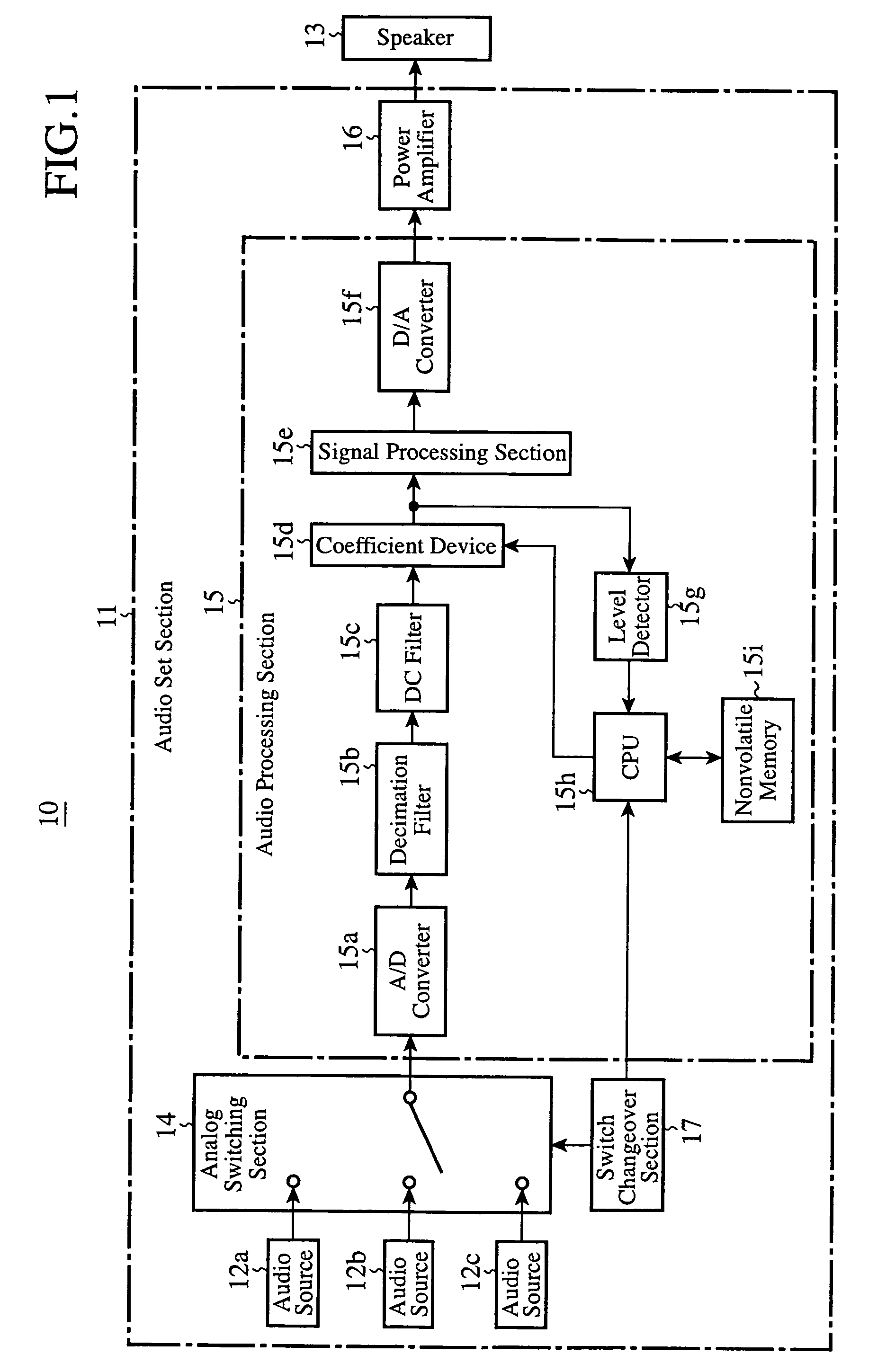
[0018]FIG. 1 is a block diagram showing a configuration of the audio system of an embodiment 1 in accordance with the present invention. The audio system 10 shown in FIG. 1 is mounted on a vehicle, for example. The audio system 10 includes an audio set section 11 having a plurality of audio sources 12a-12c, and a speaker 13 connected thereto.

[0019]In the example shown in FIG. 1, the audio source 12a is a radio receiver, the audio source 12b is a CD player, and the audio source 12c is a cassette player. These audio sources 12a-12c are connected to an audio processing section 15 via an analog switching section (SW) 14. As will be described later, the audio processing section 15 processes the input signal (audio signal) supplied via the SW 14, and outputs it as a processed signal. The processed signal is amplified by a power amplifier 16 and is output from the speaker 13 as the audio.

[0020]In the example shown in FIG. 1, the audio processing section 15 includes an A / D converter 15a, de...

embodiment 2

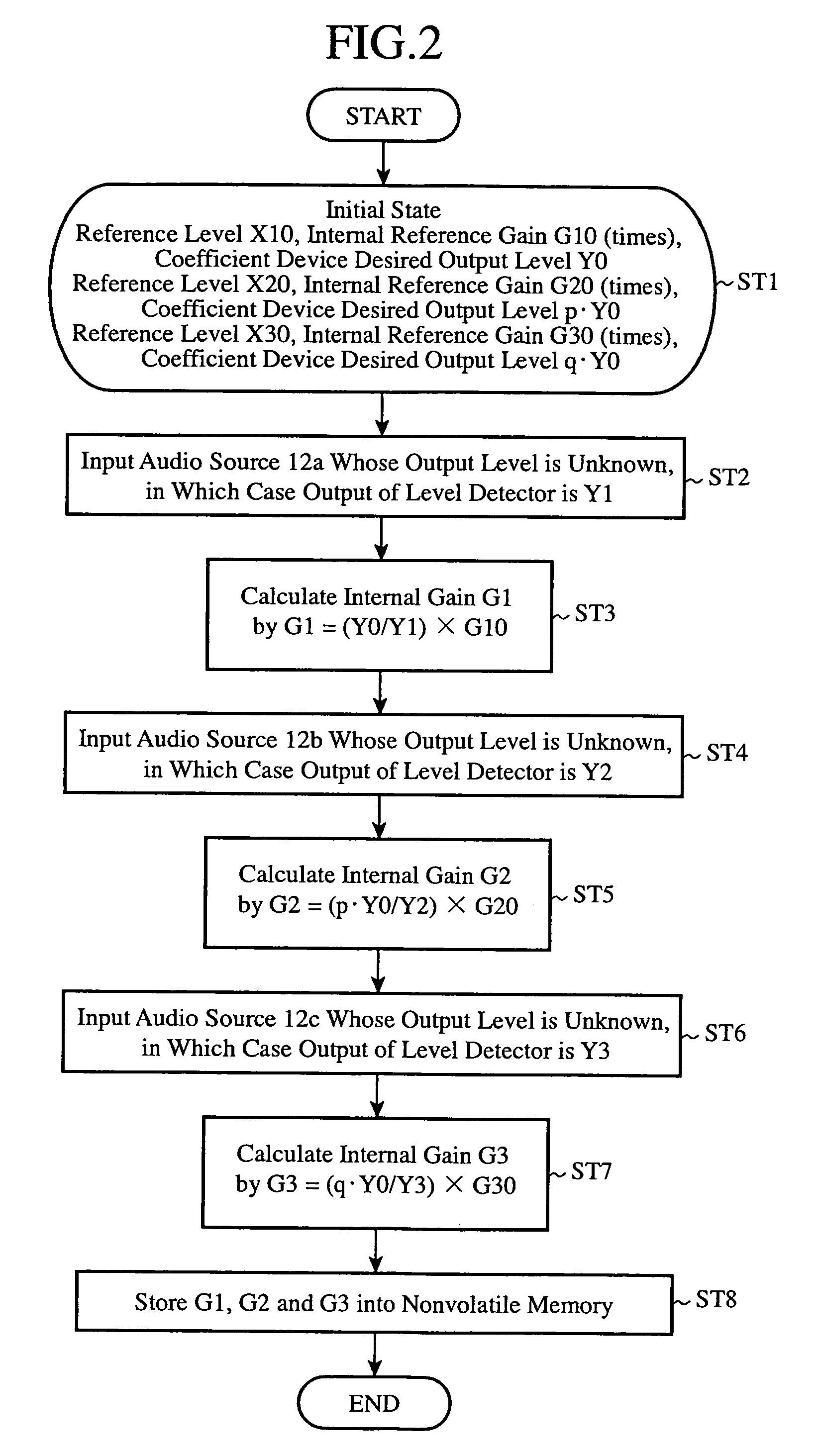
[0039]Referring to FIG. 1, the output level adjustment will now be described at the switching from the audio source, whose audio signal is listened to at present, to another audio source. It is assumed in the embodiment 2 that although the CPU has functions different from those of the embodiment 1, it is denoted by the same reference symbol for convenience of explanation, and that the nonvolatile memory 15i stores the internal gains corresponding to the audio sources 12a, 12b and 12c.

[0040]Referring to FIG. 4 and FIG. 5, the CPU 15h includes a timer 21, averaging section (averaging means) 22, arithmetic section (arithmetic means) 23, coefficient determining section (gain determining means) 24, dividing section 25, and gradually increasing section (gain setting varying means) 26 as shown in FIG. 4. Assume that the internal gain is GAV1 while the audio signal output from one of the audio sources 12a-12c is listened to (for example, the audio signal output from the audio source 12a is...


PUM


Abstract

An audio system 10 has a plurality of audio sources 12a-12c for outputting audio signals different from each other. A coefficient device 15d adjusts the gain of the audio signal output from one of the audio sources. A nonvolatile memory 15i stores, as internal gains, gains to be set to the coefficient device in correspondence with the audio sources. When a switch changeover section 17 selects one of the audio sources, the CPU 15h reads from the nonvolatile memory the internal gain corresponding to the audio source selected, and sets the internal gain to the coefficient device.

Description

TECHNICAL FIELD[0001]The present invention relates to an audio system for selectively outputting sounds from a plurality of audio sources, and particularly to an audio system capable of carrying out volume control smoothly when changing selection of the audio source.BACKGROUND ART[0002]Generally, as for an audio system including a plurality of audio sources such as a radio, cassette player and CD player, a user must carry out volume control every time he or she selects the audio source to adjust the volume of a speaker at a desired level. In other words, since the volume level varies in accordance with the audio source, the user must perform the volume control every time the audio source is selected, and the volume control is usually troublesome.[0003]To eliminate such trouble as the volume control, there is an apparatus, for example, which compares a set volume level stored in a volume level memory circuit with a volume level of an audio signal detected by a volume level detecting ...

Claims


Application Information

Patent Timeline
Patent Type & Authority Patents(United States)
IPC IPC(8): H03G3/00
CPCH03G3/001H03G3/02G06F3/165
Inventor NAKATA, KAZUHIRO
Owner MITSUBISHI ELECTRIC CORP
Learn More