
A water quality sampling rack for hydrological survey

A sampling rack and water quality technology, applied in the direction of sampling devices, etc., can solve problems such as pollution, limited use, time-consuming and laborious sampling successively, and achieve the effects of reducing mutual influence, improving accuracy, and convenient control

Active Publication Date: 2021-04-06
NORTH CHINA UNIV OF WATER RESOURCES & ELECTRIC POWER
View PDF10 Cites 0 Cited by
  • Summary
  • Abstract
  • Description
  • Claims
  • Application Information

AI Technical Summary

Problems solved by technology

[0002] Surface water needs to be sampled at different depths in hydrological surveys. Sampling is time-consuming and laborious. The existing water quality sampling racks have great limitations and cannot meet the sampling of surface water at different depths. During the sampling process, it is impossible to observe the samples collected in the sampling bottle under the turbid water source. Therefore, it is impossible to control the amount of collected sample liquid, and when sampling in layers at the same time, when the sample liquid enters the sampling bottle, the air in the sampling bottle will be discharged to generate air bubbles, making the water source turbid, and the water of different depths will be mixed. The sample liquid of the corresponding layer is polluted by the sample liquid of the adjacent layer, which seriously affects the results of hydrological survey and cannot meet the actual needs, so we invented a water quality sampling rack for hydrological survey

Method used


Image

  • A water quality sampling rack for hydrological survey
  • A water quality sampling rack for hydrological survey
  • A water quality sampling rack for hydrological survey

Examples


Embodiment Construction

[0014] In order to make the purpose, technical solutions and advantages of the embodiments of the present invention clearer, the technical solutions in the embodiments of the present invention will be clearly and completely described below in conjunction with the drawings in the embodiments of the present invention. Obviously, the described embodiments It is a part of embodiments of the present invention, but not all embodiments. Based on the embodiments of the present invention, all other embodiments obtained by persons of ordinary skill in the art without creative efforts fall within the protection scope of the present invention.

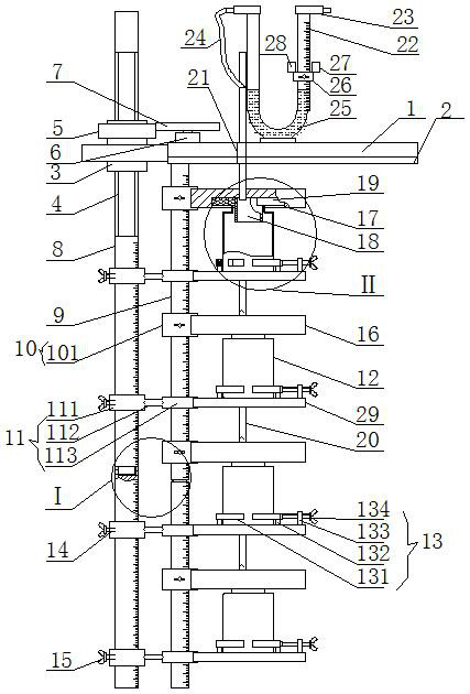
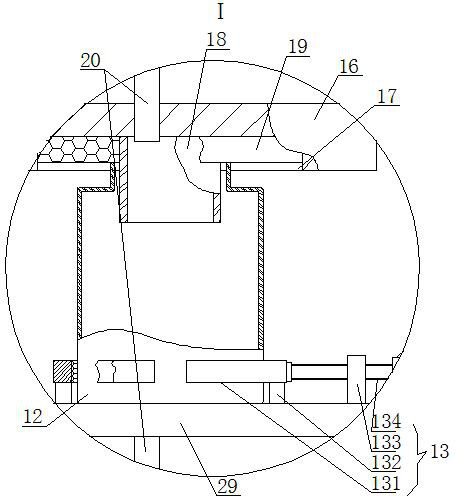
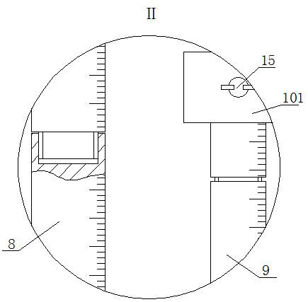
[0015]A hydrological survey water quality sampling rack, as shown in the figure, includes a base 1, a floating plate 2 is fixedly installed on the bottom side of the base 1, a vertical screw nut 3 is installed on the middle bearing on the left side of the base 1, and the inner thread of the screw nut 3 is installed with a wire Rod 4, ring gear 5 i...


PUM


Abstract

A water quality sampling rack for hydrological survey, comprising a base, a floating plate is fixedly installed on the bottom side of the base, a vertical screw nut is installed on the middle bearing on the left side of the base, a screw rod is installed on the internal thread of the screw nut, and a ring gear is fixedly installed on the upper end of the outer circumference of the screw nut , the motor is fixedly installed on the left end of the top side of the base, the gear is fixedly installed on the upper end of the motor shaft, the gear meshes with the ring gear, the lower end of the screw rod is fixedly connected to the upper end of the first vertical rod, and the left end of the bottom side of the base is fixedly connected to the second vertical rod. On the upper end, several first adjustment devices are respectively movably installed on the outer periphery of the second vertical rod. Take the device out of the survey water source, and then make the motor rotate forward until the standpipes are respectively pulled out from the corresponding sampling bottles, and then the sampling bottles are respectively removed from the corresponding sampling bottle fixing devices to complete a sampling; The first adjusting device and the fixing plate are taken off from the second vertical rod, which is convenient for cleaning the rubber pad and the vertical pipe, and is convenient for the secondary use of the device.

Description

technical field [0001] The invention belongs to the field of hydrological survey equipment, in particular to a water quality sampling frame for hydrological survey. Background technique [0002] Surface water needs to be sampled at different depths in hydrological surveys. Sampling is time-consuming and laborious. The existing water quality sampling racks have great limitations and cannot meet the sampling of surface water at different depths. During the sampling process, it is impossible to observe the samples collected in the sampling bottle under the turbid water source. Therefore, it is impossible to control the amount of collected sample liquid, and when sampling in layers at the same time, when the sample liquid enters the sampling bottle, the air in the sampling bottle will be discharged to generate air bubbles, making the water source turbid, and the water of different depths will be mixed. The sample liquid of the corresponding layer is polluted by the sample liquid...

Claims


Application Information

Patent Timeline
Patent Type & Authority Patents(China)
IPC IPC(8): G01N1/10
CPCG01N1/10
Inventor 曹连海赵荣钦李跃鹏魏冲段鹏飞姚伦广王志齐
Owner NORTH CHINA UNIV OF WATER RESOURCES & ELECTRIC POWER
Learn More