
Video compression circuit and method thereof

a video compression circuit and video technology, applied in the field of video compression circuits, can solve the problems of data not being compressed before the input video memory is fulfilled, the cost of the video compression chip also increases, and the processing delay time of input video signals is shortened

Active Publication Date: 2012-10-23
QUANTA COMPUTER INC
View PDF9 Cites 21 Cited by
  • Summary
  • Abstract
  • Description
  • Claims
  • Application Information

AI Technical Summary

Benefits of technology

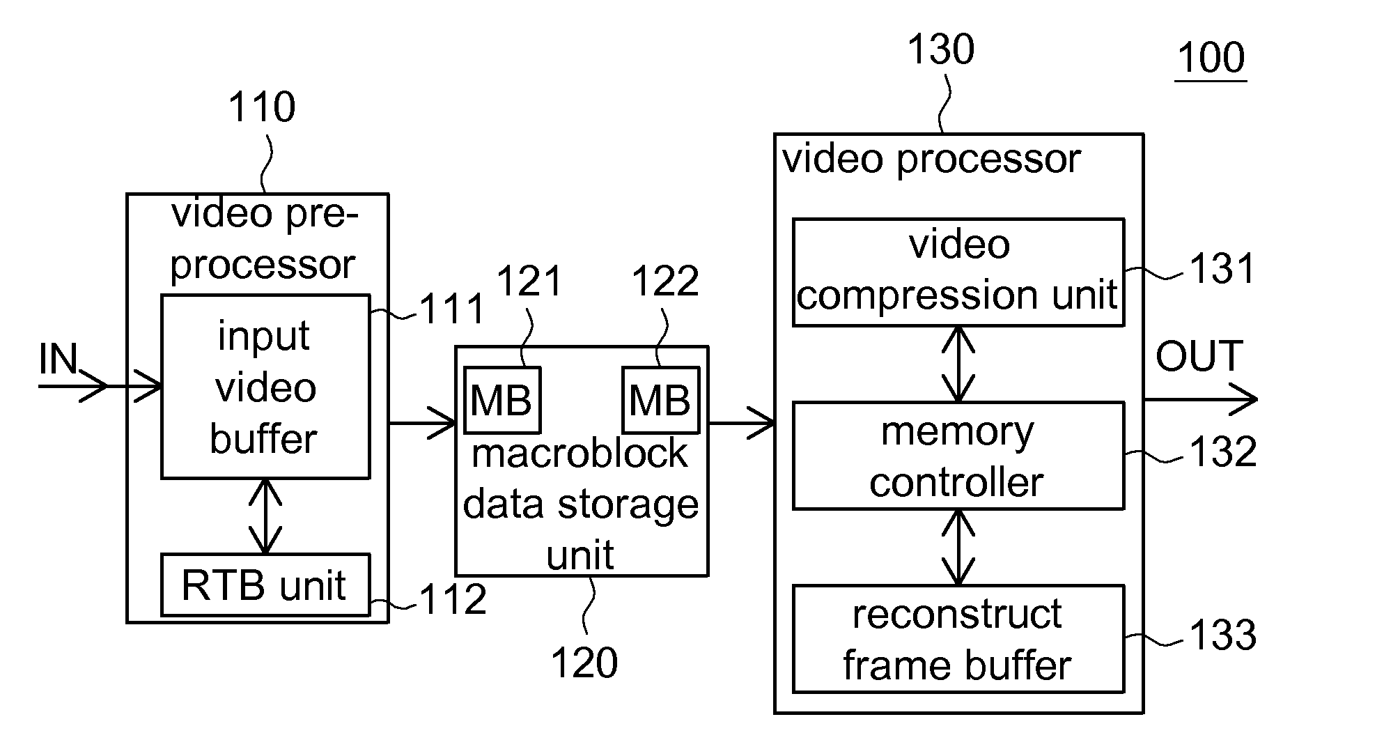
The invention is a video compression circuit and method that reduces processing delay time and hardware cost. It includes a video pre-processor, a macroblock data storage unit, and a video processor. The video pre-processor converts the input video signal to generate macroblock data, which is then stored in the macroblock data storage unit. The video processor reads the stored macroblock data and compresses it to generate an output video signal. This results in a faster processing time and a more efficient use of memory.

Problems solved by technology

Consequently, the cost for the memory in a video compression circuit is increased.
Thus, the cost of the video compression chip also increases.
Besides, according to generally known technology, data cannot be compressed before the input video memory is fulfilled (that is, one frame is completely inputted).
Therefore, the delay time is too long (that is, the delay time is about the time length of one frame) and the compression rate is too low.

Method used


Image

  • Video compression circuit and method thereof
  • Video compression circuit and method thereof
  • Video compression circuit and method thereof

Examples


Embodiment Construction

[0020]Examples of the invention is capable of largely reducing the capacity required for the input video memory and the reconstruct video memory, hence effectively reducing hardware cost for the video compression circuit. Furthermore, data compression can start immediately after just a part of an input frame is received, hence largely shortening processing delay time for input video.

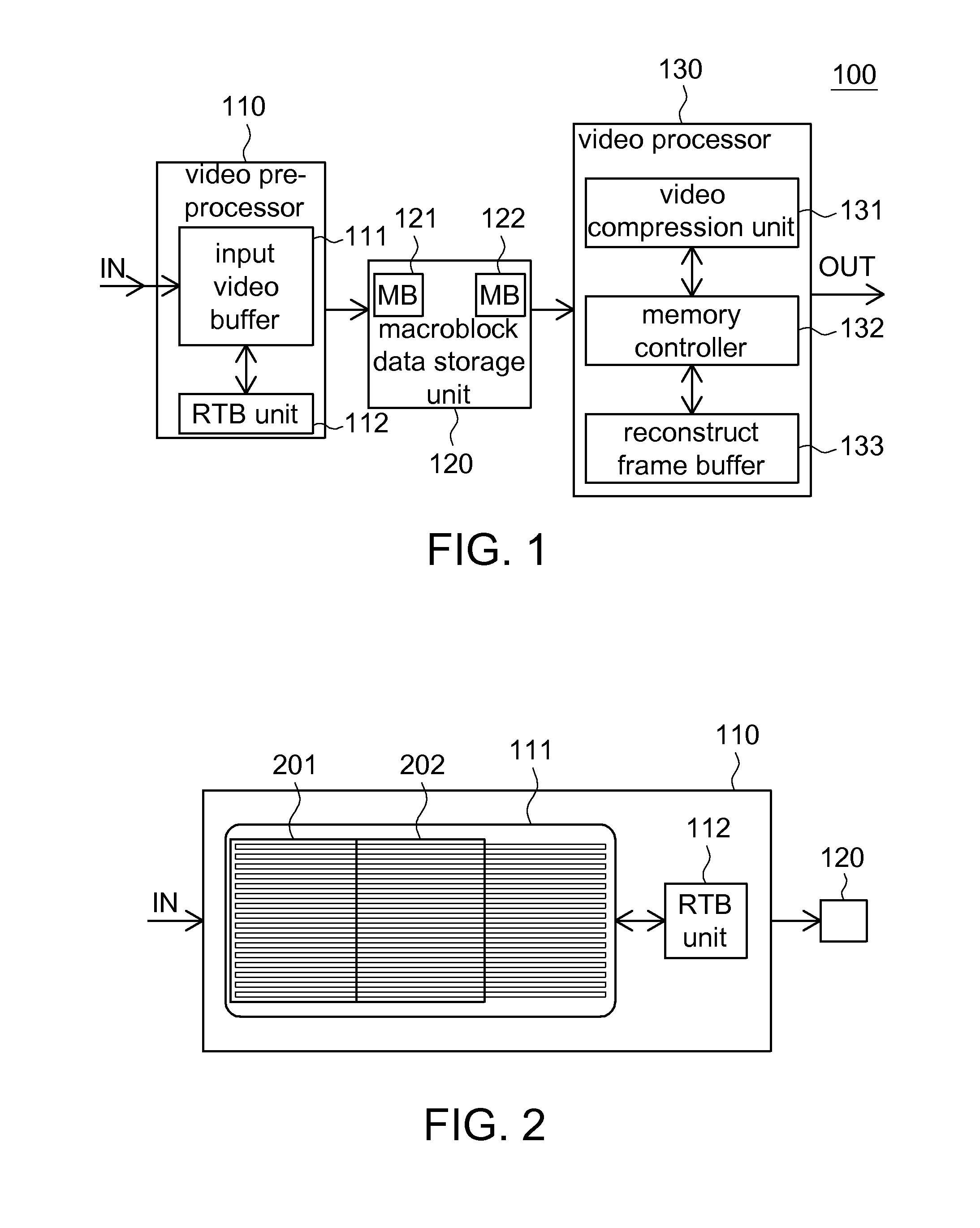
[0021]Referring to FIG. 1, a block diagram of a video compression circuit 100 according to an embodiment of the invention is shown. As indicated in FIG. 1, the video compression circuit 100 at least includes a video pre-processor 110, a macroblock data storage unit 120 and a video processor 130. The video pre-processor 110 at least includes an input video buffer 111 and a raster to block (RTB) unit 112. The macroblock data storage unit 120 at least includes several macroblock buffers (MB) exemplified by macroblock buffers (MB) 121 and 122. The video processor 130 at least includes a video compression uni...


PUM


Abstract

A video compression circuit including a video pre-processor, a macroblock data storage unit and a video processor is provided. When fulfilled by an input video signal, the video pre-processor converts the input video signal to generate a macroblock data. The macroblock data storage unit alternatively and temporally stores the macroblock data generated from the video pre-processor. The video processor alternatively reads the macroblock data stored in the macroblock data storage unit, and compresses the readout macroblock data to an output video signal.

Description

[0001]This application claims the benefit of Taiwan application Serial No. 98107944, filed Mar. 11, 2009, the subject matter of which is incorporated herein by reference.BACKGROUND OF THE INVENTION[0002]1. Field of the Invention[0003]The invention relates in general to a video compression circuit and a method thereof, and more particularly to a video compression circuit and a method thereof, capable of reducing circuit cost and shortening processing delay time.[0004]2. Description of the Related Art[0005]Along with the popularity of network, AV streaming technology is now widely used in consumer products. As consumers' expectation of video quality is getting higher and higher, even superior video compression technologies such as MPEG4 and H.264 are provided for processing (compressing / decompressing) high resolution images. During video compression, input video signals (that is, original video signals) and reconstructed video signals (that is, compressed video signals) are stored in ...

Claims


Application Information

Patent Timeline
Patent Type & Authority Patents(United States)
IPC IPC(8): G06F12/06
CPCH04N19/176H04N19/61H04N19/85H04N19/433H04N19/426
Inventor TSENG, HUAN-CHUNCHAO, WEI-MINLAI, KUAN-TINGLIU, PAI-CHIN
Owner QUANTA COMPUTER INC
Learn More