Photoemission induced electron ionization

a technology of electron ionization and photoemission, which is applied in the field of detection apparatuses, can solve the problems of not being able to address the total electron flux, not being able to use as an ionization source, and greatly reducing the intensity of the electron beam

Active Publication Date: 2012-10-16
RAPISCAN SYST INC (US)
View PDF5 Cites 11 Cited by
  • Summary
  • Abstract
  • Description
  • Claims
  • Application Information

AI Technical Summary

Problems solved by technology

These closed ion sources achieve a higher density of electrons and gaseous sample; however, the intensity of the electron beam is greatly reduced due to inefficiencies in the transmission through the slit.
However lasers are very complex and expensive and therefore not practical for a general purpose chemical analysis device.
Furthermore the UV lasers are invariably pulsed lasers and therefore do not allow a continuous beam of electrons, which is desirable for most common methods of GC-MS analysis and direct sampling MS analysis.
However, this method does not address total electron flux, or use as an ionization source.
U.S. Pat. No. 4,713,548 issued to Kim discloses a photoelectron emitter comprising a UV light source and photocathode to create negative ions; however, this invention does not disclose or teach how to achieve positive ionization or a combination of ionizations.
However, this patent, nor any of the others referenced disclose or teach how to achieve a narrow energy electron beam, convenient replacement without disrupting the vacuum, integration with a GC sampling system, nor the combination of low and medium pressure operation along with the combination of PE-EI and PI.

Method used


Image

  • Photoemission induced electron ionization
  • Photoemission induced electron ionization
  • Photoemission induced electron ionization

Examples


Embodiment Construction

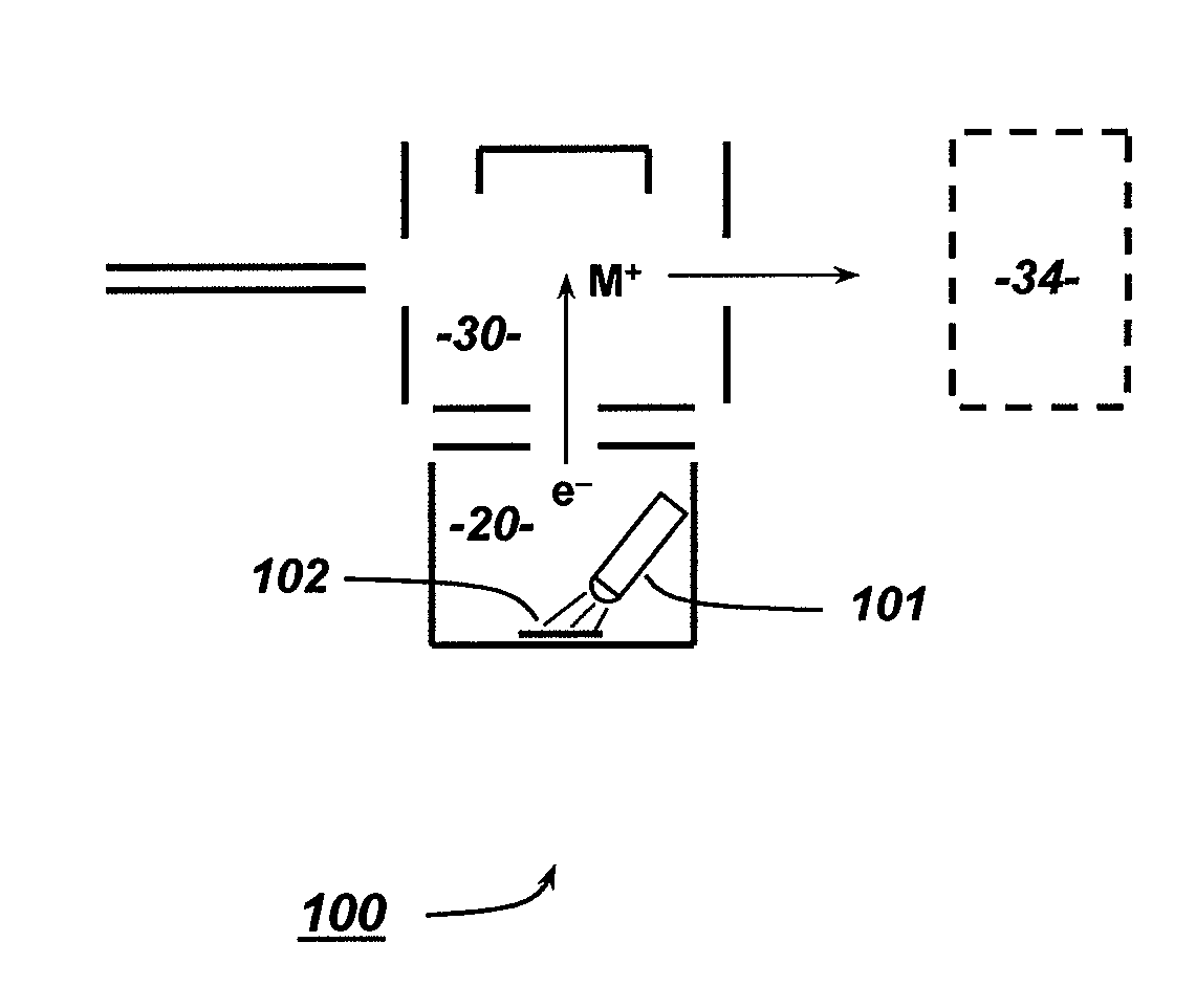
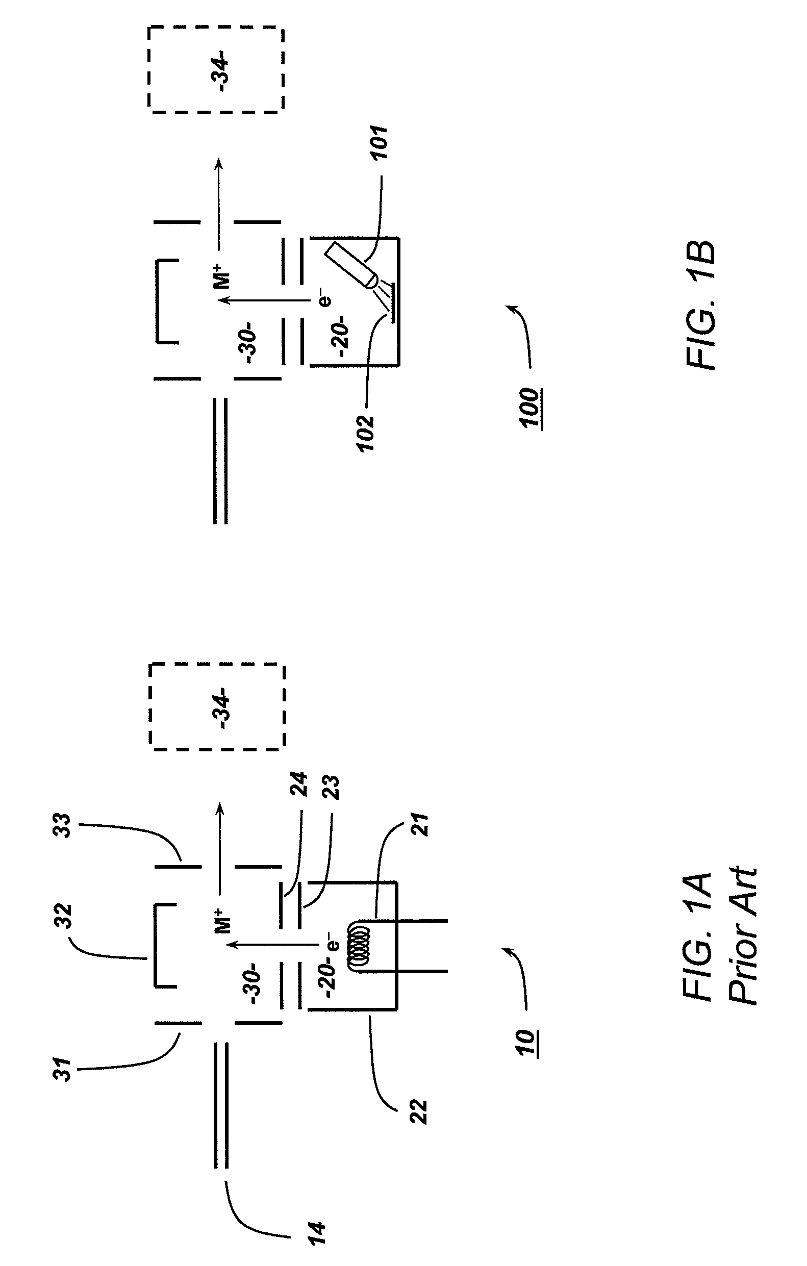
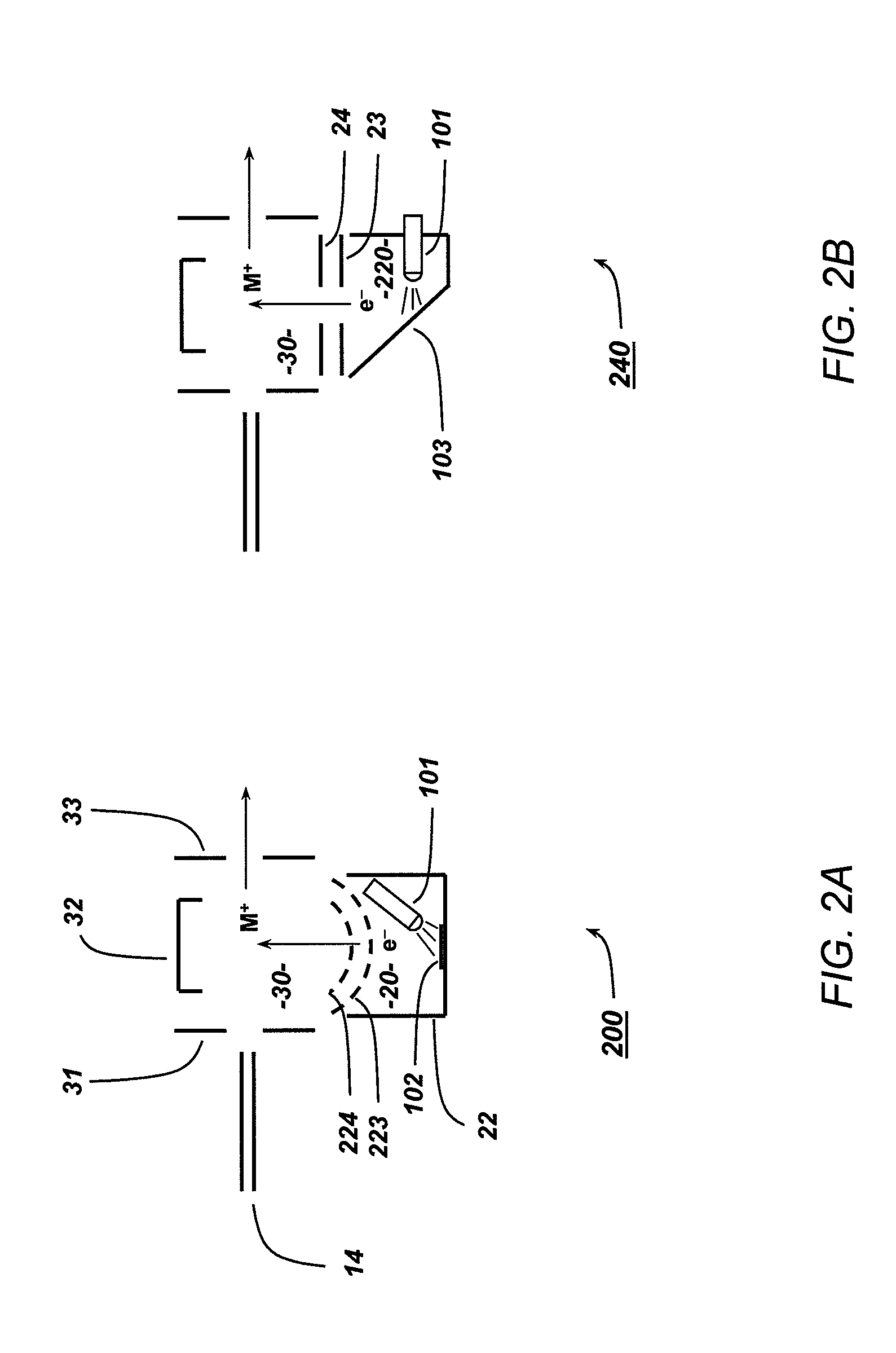
[0026]Disclosed is a monitor that can detect at least one molecule. The monitor includes a housing with a passage that can receive a sample, and a photocathode that is located within the housing. The monitor also includes a first ultraviolet light source that can direct ultraviolet light onto the photocathode to create electrons that ionize molecules within the sample, and a detector that is coupled to the housing to detect at least one ionized molecule. The monitor enables electron ionization (EI) of a sample for chemical analysis without the disadvantages of current methods that use a hot filament or other thermal cathode devices. The ionization device is especially useful for GC-MS instrumentation since it can provide highly fragmented ions, which are useful for structure analysis and for identifying molecules against an EI data base. However, it can also provide a high yield of unfragmented ions, which are important for the emerging application of GC-MS / MS, wherein instead of fr...


PUM


Abstract

A monitor that can detect at least one molecule. The monitor includes a housing with a passage that can receive a sample, and a photocathode that is located within the housing. The monitor also includes a first ultraviolet light source that can direct ultraviolet light onto the photocathode to create electrons that ionize molecules within the sample, and a detector that is coupled to the housing to detect at least one ionized molecule. The monitor enables electron ionization (EI) of a sample for chemical analysis without the disadvantages of current methods that use a hot filament or other thermal cathode devices.

Description

CROSS REFERENCE TO RELATED APPLICATION[0001]This application claims priority to Application No. 61 / 326,524 filed on Apr. 21, 2010.BACKGROUND OF THE INVENTION[0002]1. Field of the Invention[0003]The present invention relates to the field of detection apparatuses used to screen for the presence of explosives and other chemical entities.[0004]2. Background Information[0005]Mass spectrometry (MS) is one of the most important analytical methods for analyzing samples and materials for chemical composition. A main component of a MS instrument is the ionization source. Ionization sources are also used for other analytical instrumentation such as ion mobility spectrometry (IMS). There are many types of ionization sources used in these instruments depending on the analysis applications, and also the methods and types of molecules that are being analyzed.[0006]There has been new developments in ionization sources for MS instruments that are based on atmospheric pressure ionization (API). These...

Claims


Application Information

Patent Timeline
Patent Type & Authority Patents(United States)
IPC IPC(8): H01J49/10H01J27/20
CPCH01J49/08
Inventor SYAGE, JACK A.VILKOV, ANDREY N.
Owner RAPISCAN SYST INC (US)
Why Eureka
Try Eureka