
Implementing forward tracing to reduce pessimism in static timing of logic blocks laid out in parallel structures on an integrated circuit chip

a technology of parallel structure and logic block, applied in the direction of error detection/correction, program control, instruments, etc., can solve the problems of timing pessimism, significant variation penalties of logic paths that cross from one clock tree to the other clock tree, and incomplete topology not fitting inside the bounding box, so as to reduce pessimism and negative

Active Publication Date: 2012-09-18
MARVELL ASIA PTE LTD
View PDF45 Cites 4 Cited by
  • Summary
  • Abstract
  • Description
  • Claims
  • Application Information

AI Technical Summary

Benefits of technology

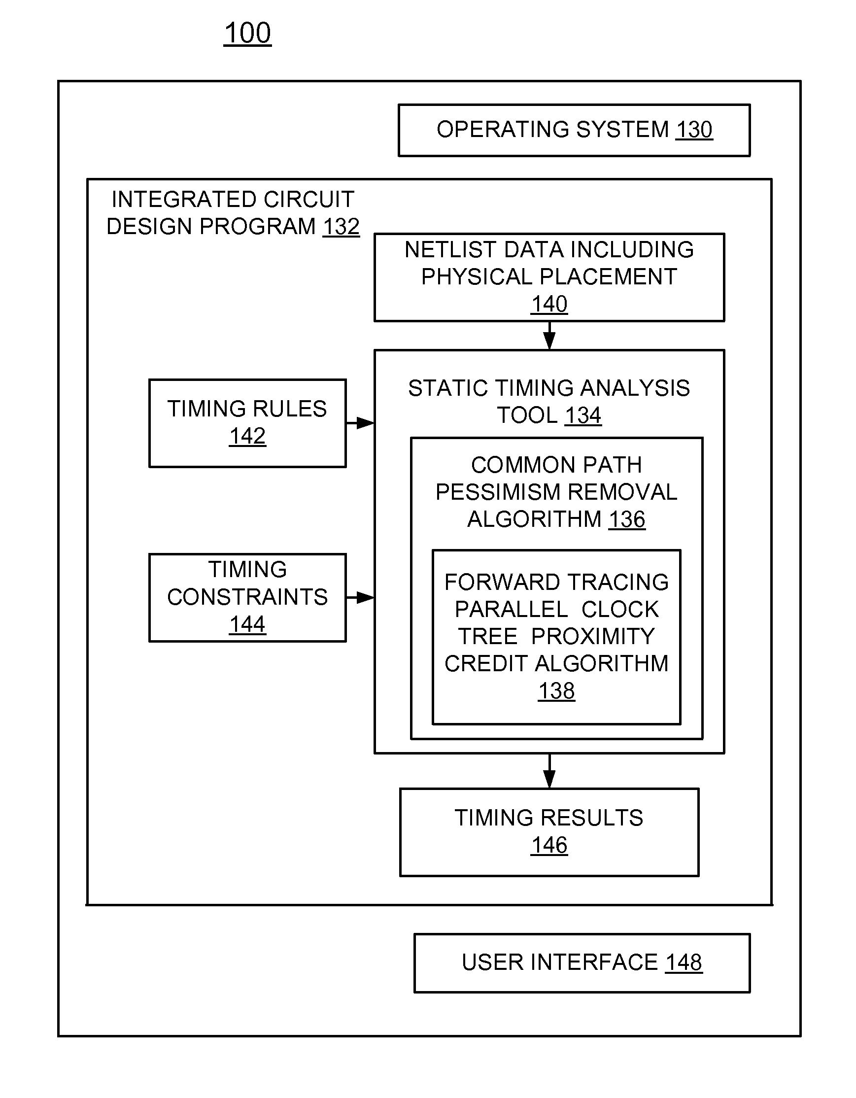
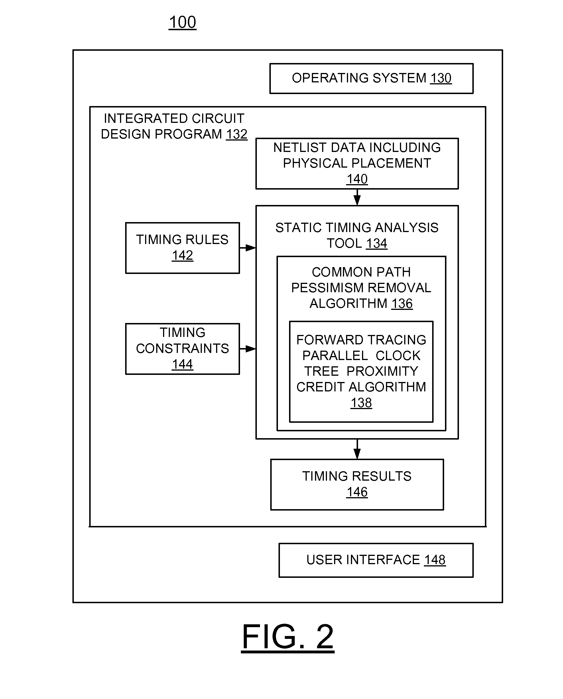
The present invention provides a method, system, and computer program product for reducing pessimism in static timing of logic blocks on an integrated circuit chip. This is done by using forward tracing and a common path pessimism removal algorithm enhanced by a proximity credit algorithm that uses forward tracing. The method involves analyzing data for a table of proximity-related pessimism values and identifying which blocks may affect the timing of a test. The amount of pessimism is then computed for each block and a proximity credit is determined to improve the timing slack on the test. The technical effect of this invention is to reduce pessimism in static timing and improve the performance of integrated circuit chips.

Problems solved by technology

When using this sort of parallel clock tree structure, logic paths that cross from one of the clock trees to the other clock tree can suffer from significant variation penalties due to the large number of clock gates that are not common between the latches involved.
Timing pessimism results when considering delay variation along common segments of clock paths.
However, these tools require all gates, which are not common between source and sink latch to be inside a bounding box.
In conventional topology, individual pairs of gates would fit inside a bounding box, but the complete topology does not fit inside the bounding box.

Method used


Image

  • Implementing forward tracing to reduce pessimism in static timing of logic blocks laid out in parallel structures on an integrated circuit chip
  • Implementing forward tracing to reduce pessimism in static timing of logic blocks laid out in parallel structures on an integrated circuit chip
  • Implementing forward tracing to reduce pessimism in static timing of logic blocks laid out in parallel structures on an integrated circuit chip

Examples


Embodiment Construction

[0016]In the following detailed description of embodiments of the invention, reference is made to the accompanying drawings, which illustrate example embodiments by which the invention may be practiced. It is to be understood that other embodiments may be utilized and structural changes may be made without departing from the scope of the invention.

[0017]The terminology used herein is for the purpose of describing particular embodiments only and is not intended to be limiting of the invention. As used herein, the singular forms “a”, “an” and “the” are intended to include the plural forms as well, unless the context clearly indicates otherwise. It will be further understood that the terms “comprises” and / or “comprising,” when used in this specification, specify the presence of stated features, integers, steps, operations, elements, and / or components, but do not preclude the presence or addition of one or more other features, integers, steps, operations, elements, components, and / or gr...


PUM


Abstract

A method, system and computer program product are provided for implementing forward tracing to reduce pessimism in static timing of logic blocks laid out in parallel structures on an integrated circuit chip. A common path pessimism removal algorithm is enhanced by a forward tracing parallel clock tree proximity credit algorithm that uses forward tracing, and computes a proximity credit that is applied to reduce pessimism in the static timing.

Description

FIELD OF THE INVENTION[0001]The present invention relates generally to the field of static timing analysis of integrated circuit design, and more particularly, relates to a method, system and computer program product for implementing forward tracing to reduce pessimism in static timing of logic blocks laid out in parallel structures on an integrated circuit chip.DESCRIPTION OF THE RELATED ART[0002]A static timing tool typically is used to automatically analyze the timing of an integrated circuit design to ensure that circuits meet critical timing constraints. EinsTimer, a commercially available static timing tool by International Business Machines Corporation, of Armonk, N.Y., performs static timing analysis on an integrated circuit design.[0003]In some Application Specific Integrated Circuit (ASIC) designs, clock trees are built such that synchronous clocks have parallel clock trees. This might happen if a divided clock is used. For example, some latches in the design may be clocke...

Claims


Application Information

Patent Timeline
Patent Type & Authority Patents(United States)
IPC IPC(8): G06F17/50
CPCG06F17/5031G06F2217/62G06F2217/84G06F30/3312G06F30/396G06F2119/12G06F30/3315
Inventor DARSOW, CRAIG M.HELVEY, TIMOTHY D.
Owner MARVELL ASIA PTE LTD
Learn More